Ariadne’s Network Notes
My notes are mostly Cisco things centered around these certification exams: CCNA, ENCOR, ENARSI, ENSLD and CCIE EI.
I’ve been in the Networking Industry since 2012, I’ve been an IT Person since 1999.
I’ve worked at Cisco on-and-off over the last 10y+, on teams like TAC for IOS-XR, or HTTS PS TAC for Route/Switch.
Push, Pop, and Swap are MPLS operations.
Email: ariadne@haske.org
License
This work is shared under Creative Commons Attribution-ShareAlike 4.0 International.
How to use this site
Search
Click the 🔍 button.
Set a theme
I like Ayu.
This site isn’t an authoritative
I usually cite my sources, this website is shorthand for better materials.
Parts of it are certainly wrong.
… what does that mean?
I usually do something like this
- Open a web search
site:cisco.com ios xe ospf
An alternative
- Ask your favorite LLM for the definitive Cisco Live / NANOG / IETF / Industry group slides
- Never let the LLM explain, only let it explain why you should read a specific source
Every topic has its expert. Find that person’s presentation materials.
I rarely reference someone else’s blog. I have too much distrust of how easy it is to get stuff wrong, myself included.
Why does this site exist?
- I like linking it to people on Discord
- I am very forgetful
How to Study
I do something like:
- Skim material (This is a vibe check).
- Go back over material, slower, with an eye towards the exam topics.
- Take basic notes.
- Pick a topic, create a lab with a working example.
- Find source materials, or more examples of a given technology.
- Talk with others about the topic.
- Understand the existing lab, look at debugs, logs, packets.
- Read more source Material.
- Take more advanced notes documenting observations about behavior.
- Understand where this concept fits with other related concepts …
 Image by Tidema - CC BY 4.0
References
How to Take Notes
The process
Consistency
If all your notes are in spiral bound notebooks or 3x5 cards, that’s OK, but pick a system and stick with it.
Detail
Cite your sources. You need enough to remember where something comes from.
Summarize
Do not re-create source materials.
- Record facts
- Summarize and reduce scope
- Fit your notes into your whole understanding (synthesis)
An hour long meeting? One page of notes. Don’t overdo it.
Myths
I don’t need to take notes. I can remember everything just fine
Note down what you will not remember
- Bit counts
- Packet headers
- Tiny specific interactions
You can find these details via
- Reading white-papers
- Reading RFCs
- Reading forum posts
- Doing labs
- Finding outputs
- Collecting packets
- Collecting debugs
I don’t look at my notes after I take them
Don’t take notes on stuff you’ll remember, take notes on stuff you’ll forget.
Learn what kinds of details you forget.
The notes aren’t for you six months from now, the notes are for you, six years from now.
I can’t take notes digitally, I need to write them out
You can take handwritten notes, just OCR them into digitals. The AI is decent at this.
If typing is painful consider a much nicer keyboard and something like Dvorak.
References
MIT - Notes and Notebooks - Mayfield Handbook of Technical and Scientific Writing
Berkeley - Academic Skills Resource Library | Athletic Study Center
Harvard - Note-Taking – Academic Resource Center
How to Make a Blog Like This
Be correct
I always ask myself these questions:
- Who is the authority on this?
- Is someone being paid to be correct?
- Does this activity have a following, group, conference, forum, or discord?
- Can this be tested in the lab?
- Can this behavior be observed?
- Can the behavior be documented?
- Can the behavior be diagrammed?
- Is effort tracked by a standards body? e.g., the IETF, IEEE, etc.
See The Correctness Hierarchy.
Documentation as code
This blog follows the Documentation as Code ethos.
- Create an account on GitHub
- Write articles in Markdown
- Learn Git Fundamentals
- Use Git
- Use a development environment
- Use GitHub Pages and Actions to Deploy mdBook
My development environment
I use Notepad++ with Syncthing.
When I save a file in Notepad++, Syncthing is notified of the change and propagates it to tesseract. mdBook sees the modification and rebuilds the webpage.
ariadne@tesseract:~/git/pushpopswap$ mdbook serve -n 0.0.0.0
 INFO Book building has started
 INFO Running the html backend
 INFO HTML book written to `/home/ariadne/git/pushpopswap/book`
 INFO Serving on: http://0.0.0.0:3000
 INFO Watching for changes...
 INFO Files changed: ["/home/ariadne/git/pushpopswap/src/how-to-make-a-blog-like-this.md"]
 INFO Book building has started
 INFO Running the html backend
 INFO HTML book written to `/home/ariadne/git/pushpopswap/book`
 INFO Files changed: ["/home/ariadne/git/pushpopswap/src/how-to-make-a-blog-like-this.md"]
 INFO Book building has started
 INFO Running the html backend
 INFO HTML book written to `/home/ariadne/git/pushpopswap/book`
Processing
mdBook is used to turn CommonMark into html.
These tools extend the html features, typically with JavaScript.
Preprocessing
These are tasks mdBook cannot do without addons.
Mermaid
- Javascript
- Turns text into diagrams
- Allows version control for diagrams
- SVG Adaptive
- Resize Nicely
- Light and Dark theme adaptive
Mermaid is a binary js file that gets copied to the root of the repo.
curl -sL https://cdn.jsdelivr.net/npm/mermaid@11.5.0/dist/mermaid.min.js -o mermaid.min.js
Then mdbook needs to be rebuilt:
mdbook build
GitInfo
- Injects Git Metadata into the rendered HTML articles
- Commit
- Date of Commit
- Link to Commit
- Onto every webpage
SVGBOB
- buggy
- Converts ASCII Art to a SVG
- It does this on build
mdbook-svgbob uses the above embed svgbob into mdBook
Custom Scripts
Javascript here modifies mdbook or extends mdbook to allow a better site viewing experience.
Mermaid
Mermaid lazyload
Lighthouse penalizes pages based on first content paint times.
Mermaid comes with a large binary, ~3MB: mermaid-11.15.0.min.js.
This script is put into the render blocking path. The big mermaid file is only loaded on pages with Mermaid.
Connected to:
mermaid-11.15.0.min.jssvg-zoomer.js
SVG zoomer
There are some very large diagrams on this site.
SVGs and Mermaid diagrams can’t be zoom’d natively on desktop. This script creates a fullscreen pan/zoom viewer.
- Desktop only: on mobile the browser’s own pinch-to-zoom already works; this script is disabled.
- Self-contained (Pointer Events), no libraries
Connected to:
mermaid-lazyload.js
Zoom unstick
On touch devices a sticky menu bar rides along magnified during pinch-zoom, covering the content being zoomed. This tags <html> with pinch-zoomed while zoomed in so the menu bar unsticks, then restores it when zoomed back out.
- Uses
visualViewportscale, no libraries - Keeps the search button reachable at normal zoom
SEO
This site doesn’t do great on Bing.
Stamp page mtimes
Necessary for accurate dates on pages before submitting with IndexNow.
This is run right before build.
Use-ability
Things to make the notes experience nicer.
Editable extras
- Extends mdBook’s editable code block behavior after
book.jsruns- Adds undo controls for editable non-Rust examples
- Uses code fences:
```text,editable
AI Use Statement
There is some AI use here, I generally write all the articles in my own voice.
Some diagrams are AI assisted, I go over the theory by hand.
I token maxx, balancing between $20 on Anthropic and $20 on OpenAI.
Where LLMs are used
- OCR tasks
- Diagram-to-Code tasks
- Reforming tables
- Lint
- Spelling and grammar
- Finding potential technical errors
- Rubber Ducking
- Vibe Coding
- Debugging
- Lab Implementation
Where LLMs are not used
- Theory
- Debugging
- Lab Design
- Note Taking
- Prose
- Technical Writing
The Correctness Hierarchy
This is an ordered list of how correct something tends to be, from the standpoint of a Network Engineer.
Ariadne’s maxim
The more correct a material tends to be, the harder it becomes to understand and/or access.
The list
A tier list ranking sources of technical correctness from S (most authoritative) to F (least): S is observed behavior, A is published standards, B is inventor sources, C is vendor sources, D is Wikipedia, E is content creator sources, F is vendor marketing and social media.
Terms
Published Standards — IETF Documents or IEEE documents
Inventor — The person who created it
Distinguished Engineer — Someone famous in the Industry
Content Creator — Someone making content
Examples
Using the AI to be correct is a failing grade at F-tier. Same goes for social media (let’s say, TikTok, Linkedin, Facebook, et. al)
Vendors lie when they market, so they also go to F-tier.
Textbooks are E-tier, there is no independent auditing of textbook correctness, and they are very difficult to correct once published.
If the vendor has a textbook, that’s D-tier. Usually, a certification is tied to it, so they are a touch better edited.
The vendor community is interesting, people post both very stupid questions, but also get brilliant answers. Solid C-tier.
Vendor materials can’t get above C-tier because money is always involved. Getting material published at a vendor is difficult enough.
John Moy’s book on OSPF is B-tier. Ivan’s site https://blog.ipspace.net/ is also B-tier, he’s been in the Industry forever.
The RFC for OSPFv2 is A-tier, it’s what we all refer to to check the behavior, otherwise we need to get onto a mailing list.
A setup running OSPFv2 is S-tier. It might be ancient, broken, or incorrect, but we cannot argue that it did not happen.
Git
Git is a collaborative code tool. It allows distributed development, with yourself or others.
The database that holds the code, the history of changes to the code is a repository.
Previous version control tools used diffs, which are changes or deltas between files “lines 38 to 42 have changed”, Git is snapshot based.
Every file being tracked is hashed with SHA-1, each and every time a commit is made. Git always knows if files have been changed.
The list of files and their hashes is called the Index.
Terms
Repository
.git/- AKA, Repo
- AKA, the object store
- Content Addressable Filesystem
- Key-value based. All of Git is key-value
- De-Duplicated. If two files have the same SHA-1, git stores 1 blob
- Git stores: blobs, trees, commits, and tags
- Interacted with almost purely via
git
Commits
- Takes a snapshot of the current Index
- SHA-1 entity that points to a specific tree
- Metadata: author, commiter, timestamp, messages, parent commit
- Commits are backwards chains
- All commits store the hash of previous commits
Tree
- A directory snapshot
- Mode (file type and permissions)
- Name (file or directory)
- SHA-1 (the hash)
- Trees point to blobs and other trees
Blob
- A key-value pair that represents a file
82da472f6d00dc5f0a651f33ebb320aa9c7b08d0 LICENSE- The SHA-1 is used to find the compressed content of
LICENSE
Branch
- A named pointer to a specific commit
- Commits are stored as nodes on a DAG
- Merge commits have two or more parents
- The init commit has no parents
HEAD
- A named pointer to the current branch
- In detached HEAD state, points directly to a commit
- Works like the playhead on a tapedeck
Working tree
- AKA, project directory
- AKA, user directory
- AKA, your files
- This is where project files are modified
- Directory inside
git initwas ran
The index
.git/index- AKA, staging
- AKA, cache
- AKA, pre-commit
- AKA, git’s files
- Invoked with
git add - Adding a file does two things:
- SHA-1 of the file, adding it to the Index
- Writes the blob to .git/objects/
- Files in the Index are tracked
Local files overview
Git tries to avoid touching working tree files. When a file is added, a snapshot is taken at that time.
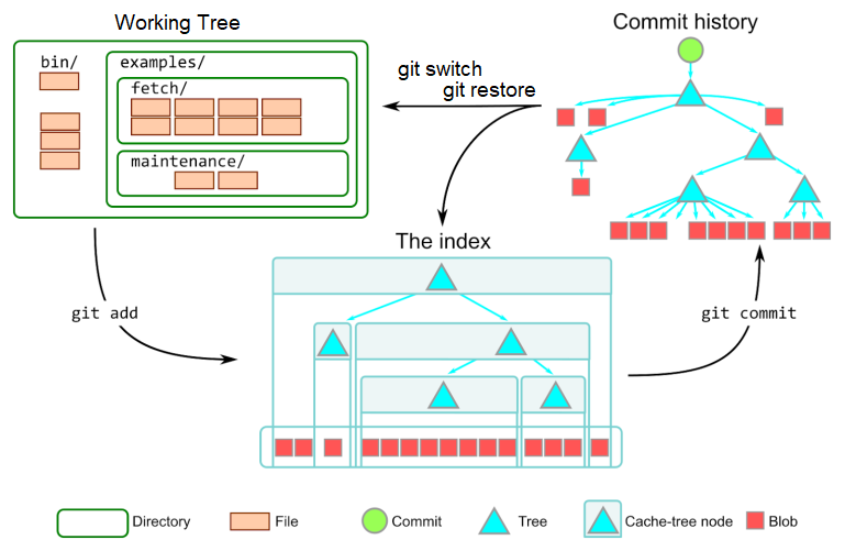
Image courtesy of Derrick Stolee.
Branch example
gitGraph
   commit id: "A"
   commit id: "B"
   commit id: "C"
   commit id: "D"
   commit id: "HEAD → E"
A, B, C, D are previous commits.
The working tree contains the files from commit E.
I think of it like a tape deck, the HEAD can be played backwards or forwards.
commit moves the HEAD forward, and reset moves the HEAD backwards.
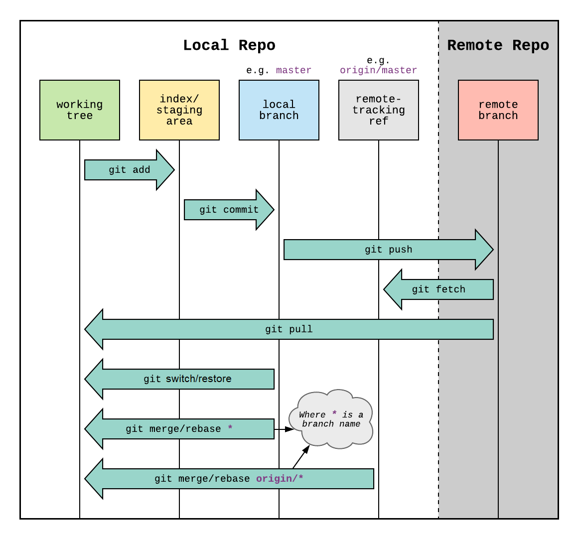
Remote and local overview
A basic example: a local repo, and a remote repo.
flowchart TD
    Remote --> Local
    Local --> Remote
The default reference for the remote repo is origin.
Local branches are referenced by name e.g. main
flowchart TD
    Remote[origin/main] --> Local
    Local[main] --> Remote
Pull
To update the local repo to match the remote, use pull
flowchart TD
    Remote[origin/main] -->|pull| Local
    Local[main] --> Remote
git pull
Push
To update the remote repo to match the local, use push
flowchart TD
    Remote[origin/main] --> Local
    Local[main] --> |push|Remote
git push
Git operations
References
Git - User-Manual Documentation
Git Merge
Warning
Do not perform
pullor amergewith uncommitted changes.
mergeis designed to combine committed changes. You can lose work.
How does merge work
E is the last shared commit.
Merge will play back the commits on both branches. If neither set of commits touches the same parts of the file, the branches are merged, and HEAD moves to the end.
gitGraph
   commit id: "D"
   commit id: "E"
   branch feature
   checkout feature
   commit id: "A"
   commit id: "B"
   commit id: "MERGE_HEAD → C"
   checkout main
   commit id: "F"
   commit id: "HEAD → G"
After the merge
gitGraph
   commit id: "D"
   commit id: "E"
   branch feature
   checkout feature
   commit id: "A"
   commit id: "B"
   commit id: "C"
   checkout main
   commit id: "F"
   commit id: "G"
   merge feature id: "HEAD → H"
Merge types
Fast forward
The default merge is called fast forward, or FF.
FF can be used when there are no local changes or local commits.
The repo was cloned previously.
Before fetch.
gitGraph
   commit id: "A"
   commit id: "B"
   commit id: "HEAD → C"
After fetch.
gitGraph
   commit id: "A"
   commit id: "B"
   commit id: "HEAD → C"
   commit id: "D"
   commit id: "E"
After merge.
git merge origin/main
gitGraph
   commit id: "A"
   commit id: "B"
   commit id: "C"
   commit id: "D"
   commit id: "HEAD → E"
Pull
pull combines fetch and merge. pull assumes a fast forward merge.
Before pull.
gitGraph
   commit id: "A"
   commit id: "B"
   commit id: "HEAD → C"
After pull.
gitGraph
   commit id: "A"
   commit id: "B"
   commit id: "C"
   commit id: "D"
   commit id: "HEAD → E"
True merge
This happens trying to update the part of a file, someone else has already updated.
-
HEADpointer stays the same -
MERGE_HEADpointer on the branch to be merged. -
What can be merged cleanly is merged.
-
Index records three versions of the files.
Ancestor,HEADandMERGE_HEAD- Files are merged in the working directory with conflict markers
<<<<<<,=======, >>>>>>`
- Files are merged in the working directory with conflict markers
-
A ref called
AUTO_MERGEgets created.
Conflict resolution
After the merge, Git will say what files need to be resolved. This is called Conflict Resolution.
To resolve:
- Open the file.
- Find the Markers.
- Delete lines you don’t want.
- Delete the markers.
Two way conflict
In Conflict.
                   Here are lines that are either unchanged from the common
                   ancestor, or cleanly resolved because only one side changed,
                   or cleanly resolved because both sides changed the same way.
                   <<<<<<< yours:sample.txt
Your change  ┌───  Conflict resolution is hard;
             └───  let's go shopping.
                   =======
    Theirs    ───  Git makes conflict resolution easy.
                   >>>>>>> theirs:sample.txt
                   And here is another line that is cleanly resolved or unmodified.
Resolved, kept local change.
                   Here are lines that are either unchanged from the common
                   ancestor, or cleanly resolved because only one side changed,
                   or cleanly resolved because both sides changed the same way.
Your change  ┌───  Conflict resolution is hard;
             └───  let's go shopping.
                   And here is another line that is cleanly resolved or unmodified.
Three way conflict
zdiff3 shows the conflict with the original text, adding the ||||||| marker.
In Conflict
                 Here are lines that are either unchanged from the common
                 ancestor, or cleanly resolved because only one side changed,
                 or cleanly resolved because both sides changed the same way.
                 <<<<<<< yours:sample.txt
      Yours ┌──  Conflict resolution is hard;
            └──  let's go shopping.
                 ||||||| base:sample.txt
Original    ┌──  or cleanly resolved because both sides changed identically.
 (Ancestor) └──  Conflict resolution is hard.
                 =======
     Theirs  ──  Git makes conflict resolution easy.
                 >>>>>>> theirs:sample.txt
                 And here is another line that is cleanly resolved or unmodified.
Resolved, kept their lines.
                 Here are lines that are either unchanged from the common
                 ancestor, or cleanly resolved because only one side changed,
                 or cleanly resolved because both sides changed the same way.
     Theirs  ──  Git makes conflict resolution easy.
                 And here is another line that is cleanly resolved or unmodified.
Conflicts resolved
This will also check the merge status.
git merge --continue
Abort A merge
merge --abort
References
Git Branch
Always name branches as lowercase, as case-sensitive branches do not work across all operating systems.
Create a new branch
git branch --copy new-branch
Create a branch from a specific branch
git branch --copy new-branch old-branch
Delete a branch
Only works if it’s fully merged.
git branch --delete dev
Delete a remote branch
Only works if it’s fully merged.
git branch --delete --remotes dev
Move a branch
git branch --move old-branch new-branch
See all branches
git branch --all
References
github - Git branch name - case sensitive or insensitive? - Stack Overflow
Git - git-branch Documentation
Git Switch
This command was added to Git in 2019 (2.23), after user feedback that checkout was destructive in some cases.
switch updates the working tree, and index to match the new branch.
Important
The destructive form of this command is
--discard-changes.
Make A new branch
git switch -c newbranch
Make A new branch from A specific commit
git switch -c newbranch <commit>
References
Git - git-switch Documentation
Git Push
Git has a default setup for where it plans to perform the push. This is the push.default.
The push.default contains the refspec.
Refspec
The refspec maps a local branch to a remote branch.
This is inside of .git/config
[remote "origin"]
        url = git@github.com:ariadne-notes/network-notes.git
        fetch = +refs/heads/*:refs/remotes/origin/*
Format of refspec
This is the fetch line from above.
- Format:
+<src>:<dst>+force update (non-fast-forward allowed)<src>source ref<dst>destination ref
Updating history
Making a change on the remote, to the commit history itself requires force.
The safer way to do this is per-branch, not the entire repo.
git push origin +main
References
Git Log
Top down, the normal view.
git log --oneline
Bottom up, good for rebasing.
git log --oneline --reverse
Decorate with active branches.
git log --oneline --decorate --graph
Decorate with all branches, even rebased ones.
git log --oneline --decorate --graph --all
Before rebasing
This can help find a commit in the event you need it again.
git log --reverse --oneline --date=short --format="%ad | %h | %an | %s" > commit-before-rebasing.txt
References
Git Rebase
Caution
rebasemodifies history.Do not rebase commits that others may have based work on.
Two branches, the start.
---
config:
  gitGraph:
    parallelCommits: true
---
gitGraph LR:
   commit id: "A"
   commit id: "B"
   commit id: "C"
   branch dev
   checkout dev
   commit id: "HEAD → E"
   checkout main
   commit id: "HEAD → D"
Normally, with two branches, we’d do a merge
Merging
---
config:
  gitGraph:
    parallelCommits: true
---
gitGraph LR:
   commit id: "A"
   commit id: "B"
   commit id: "C"
   branch dev
   checkout dev
   commit id: "HEAD → E"
   checkout main
   commit id: "D"
   merge dev id: "HEAD → F"
F is the commit the combines the diff of the endpoints of the branches main and dev.
The dev branch is just hanging out.
Rebasing
---
config:
  gitGraph:
    parallelCommits: true
---
gitGraph LR:
   commit id: "A"
   commit id: "B"
   commit id: "C"
   branch dev
   checkout dev
   commit id: "HEAD → E"
   checkout main
   commit id: "HEAD → D"
Finding the common ancestor to both branches, C we go “This is the common base, just play the diffs forward from both branches onto main”
git checkout dev
git rebase main
---
config:
  gitGraph:
    parallelCommits: true
---
gitGraph LR:
   commit id: "A"
   commit id: "B"
   commit id: "C"
   commit id: "HEAD/main → D"
   commit id: "HEAD/dev → E"
Now the HEAD for two branches main and dev are on the same branch. Main can be FF’d to move the HEAD.
git checkout main
git merge dev
---
config:
  gitGraph:
    parallelCommits: true
---
gitGraph LR:
   commit id: "A"
   commit id: "B"
   commit id: "C"
   commit id: "D"
   commit id: "HEAD/main, dev → E"
References
Git - git-rebase Documentation
Git Reset
Reset changes what commit HEAD points to. This is one way to undo a bad local commit, or a series of bad local commits.
Reset always modifies history.
Soft reset
AKA, Squashing
- Move
HEAD. - Do not modify the Index.
- Do not modify the Working Tree.
This is useful to undo local commits then re-play them as one commit.
e.g, you don’t need to git add the files are already in the Index.
git reset --soft HEAD~3
git commit
Mixed reset
Creates Intermediate Commits.
- Move
HEAD. - Reset Index to
HEAD - Do not modify the Working Tree.
Maybe you made 5 local commits but you’d prefer if it was 2.
git reset --mixed HEAD~5
git add file1.c
git add file2.c
git commit -m "Intermediate Commit 1"
git add file3.c
git add file4.c
git commit -m "Final commit"
Hard reset
Caution
This erases uncommitted work. This creates dangling local commits.
- Move
HEAD - Reset Index to
HEAD - Reset Working Tree to
HEAD
git fetch origin
git reset --hard origin/main
References
Git Remote
Necessary when cloning a repo I own usually.
Show current remotes
ariadne@tesseract:~/git/pushpopswap$ git remote -v
origin  git@github.com:ariadne-notes/pushpopswap.git (fetch)
origin  git@github.com:ariadne-notes/pushpopswap.git (push)
Set remote
git remote set-url origin git@github.com:ariadne-notes/pushpopswap.git
References
Git - git-remote Documentation
Git RM
Used to remove files from the Index, in the event they are deleted from the working tree, and need to be deleted from future commits.
Example
I’ve already deleted this file from the Working Tree, now I want to remove it from the Index.
ariadne@tesseract:~/git/network-notes$ git status
On branch main
Your branch is up to date with 'origin/main'.

Changes not staged for commit:
  (use "git add/rm <file>..." to update what will be committed)
  (use "git restore <file>..." to discard changes in working directory)
        modified:   .github/workflows/mdbook.yml
        modified:   book.toml
        deleted:    src/New Text Document.txt
git rm --cached src/New Text Document.txt
References
Git Commit
Ordinary commit
git commit -m "Here is what I did"
Amend - change the last commit message
Warning
Do not amend commits that have already been published.
git commit --amend -m "This is what I wished it said"
All
- Automatically stages all files known to the Index
- Does not add new files
git commit --all -m "Used when you don't want to manually add files
References
Git - git-commit Documentation
Git Restore
This command was added to Git in 2019 (2.23), after user feedback that checkout was destructive in some cases.
Important
These are destructive commands.
These commands should be used with -- otherwise Git doesn’t know if you want a branch, directory, or file.
-- means file.
Restore from index
- Copy a file to the working tree from the Index.
A file is staged.
git add hello.c
Work happens (in the working tree) now this file is broken.
git restore -- hello.c
Restore the index
- Copy a file to the Index from the current commit..
This “unstages” a file, the version in HEAD is restored to Index.
Equivalent to undoing git add
git restore --staged -- hello.c
Restore a file to working tree from origin
git restore --source origin/main -- hello.c
References
Git - git-restore Documentation
What is git restore and how is it different from git reset? - Stack Overflow
Git Ignore
The .gitignore file is useful for things that should not be included in Git.
# - Comments
/ - Directories, the first / is the root of the repo.
Example
This ignores the file itself, and the directory /book which is the build artifacts when mdbook is run.
ariadne@tesseract:~/git/network-notes$ cat .gitignore
.gitignore
/book
References
Git Hub Commands
Creating the repo on GitHub
This is done inside the directory after it’s created.
Auth needs to be already working.
gh repo create ariadne-notes/wifi-charts --remote=origin --public --push --source=.
References
GitHub CLI | Take GitHub to the command line
TCP
Connection oriented.
Header
 0                   1                   2                   3
 0 1 2 3 4 5 6 7 8 9 0 1 2 3 4 5 6 7 8 9 0 1 2 3 4 5 6 7 8 9 0 1
┌───────────────────────────────┬───────────────────────────────┐
│          Source Port          │       Destination Port        │
├───────────────────────────────┴───────────────────────────────┤
│                        Sequence Number                        │
├───────────────────────────────────────────────────────────────┤
│                    Acknowledgment Number                      │
├───────┬───────┬─┬─┬─┬─┬─┬─┬─┬─┬───────────────────────────────┤
│  Data │       │C│E│U│A│P│R│S│F│                               │
│ Offset│ Rsrvd │W│C│R│C│S│S│Y│I│            Window             │
│       │       │R│E│G│K│H│T│N│N│                               │
├───────┴───────┴─┴─┴─┴─┴─┴─┴─┴─┼───────────────────────────────┤
│           Checksum            │         Urgent Pointer        │
├───────────────────────────────┴───────────────────────────────┤
│                           [Options]                           │
├───────────────────────────────────────────────────────────────┤
│                                                               │
│                             Data                              │
│                                                               │
└───────────────────────────────────────────────────────────────┘
Flags
- Congestion Window Reduced
- ECN-Echo
- Urgent
- Acknowledgment
- Push
- Reset
- Synchronize
- Final
References
RFC 9293: Transmission Control Protocol (TCP) | RFC Editor
UDP
UDP checksum
UDP does try to send error-free packets by including a checksum, the below via the RFC
Checksum is the 16-bit one’s complement of the one’s complement sum of a pseudo header of information from the IP header, the UDP header, and the data, padded with zero octets at the end (if necessary) to make a multiple of two octets.
…
If the computed checksum is zero, it is transmitted as all ones (the equivalent in one’s complement arithmetic). An all zero transmitted checksum value means that the transmitter generated no checksum (for debugging or for higher level protocols that don’t care).
UDP header
 0                   1                   2                   3
 0 1 2 3 4 5 6 7 8 9 0 1 2 3 4 5 6 7 8 9 0 1 2 3 4 5 6 7 8 9 0 1
┌────────────────────────────────┬───────────────────────────────┐
│          Source Port           │       Destination Port        │
├────────────────────────────────┼───────────────────────────────┤
│            Length              │           Checksum            │
├────────────────────────────────┴───────────────────────────────┘
│          Data Octets
└────────────────────────────────►
TFTP read request
Frame 115: 69 bytes on wire (552 bits), 69 bytes captured (552 bits) on interface -, id 0
    Internet Protocol Version 4, Src: 10.0.10.22, Dst: 10.0.10.33
    User Datagram Protocol, Src Port: 52775, Dst Port: 69
        Source Port: 52775
        Destination Port: 69
        Length: 31
        Checksum: 0x4aed [correct]
        [Checksum Status: Good]
        [Stream index: 0]
        [Timestamps]
        UDP payload (23 bytes)
    Trivial File Transfer Protocol
        Opcode: Read Request (1)
        Source File: startup-config
        Type: octet
TFTP data packet
Frame 116: 562 bytes on wire (4496 bits), 562 bytes captured (4496 bits) on interface
    Internet Protocol Version 4, Src: 10.0.10.33, Dst: 10.0.10.22
    User Datagram Protocol, Src Port: 52590, Dst Port: 52775
        Source Port: 52590
        Destination Port: 52775
        Length: 524
        Checksum: 0xde83 [correct]
        [Checksum Status: Good]
        [Stream index: 1]
        [Timestamps]
        UDP payload (516 bytes)
    Trivial File Transfer Protocol
        Opcode: Data Packet (3)
        [Destination File: startup-config]
        [Read Request in frame 115]
        Block: 1
        [Full Block Number: 1]
    Data (512 bytes)

    0000  0a 21 0a 21 20 4c 61 73 74 20 63 6f 6e 66 69 67   .!.! Last config
    0010  75 72 61 74 69 6f 6e 20 63 68 61 6e 67 65 20 61   uration change a
    0020  74 20 30 35 3a 31 31 3a 31 35 20 55 54 43 20 53   t 05:11:15 UTC S
    0030  61 74 20 4a 75 6c 20 38 20 32 30 32 33 0a 21 0a   at Jul 8 2023.!.
    0040  76 65 72 73 69 6f 6e 20 31 35 2e 32 0a 73 65 72   version 15.2.ser
    0050  76 69 63 65 20 74 69 6d 65 73 74 61 6d 70 73 20   vice timestamps
    0060  64 65 62 75 67 20 64 61 74 65 74 69 6d 65 20 6d   debug datetime m
    0070  73 65 63 0a 73 65 72 76 69 63 65 20 74 69 6d 65   sec.service time
    0080  73 74 61 6d 70 73 20 6c 6f 67 20 64 61 74 65 74   stamps log datet
    0090  69 6d 65 20 6d 73 65 63 0a 6e 6f 20 73 65 72 76   ime msec.no serv
    00a0  69 63 65 20 70 61 73 73 77 6f 72 64 2d 65 6e 63   ice password-enc
    00b0  72 79 70 74 69 6f 6e 0a 73 65 72 76 69 63 65 20   ryption.service
    00c0  63 6f 6d 70 72 65 73 73 2d 63 6f 6e 66 69 67 0a   compress-config.
    00d0  21 0a 68 6f 73 74 6e 61 6d 65 20 53 57 33 0a 21   !.hostname SW3.!
    00e0  0a 62 6f 6f 74 2d 73 74 61 72 74 2d 6d 61 72 6b   .boot-start-mark
    00f0  65 72 0a 62 6f 6f 74 2d 65 6e 64 2d 6d 61 72 6b   er.boot-end-mark
    0100  65 72 0a 21 0a 21 0a 6c 6f 67 67 69 6e 67 20 64   er.!.!.logging d
    0110  69 73 63 72 69 6d 69 6e 61 74 6f 72 20 45 58 43   iscriminator EXC
    0120  45 53 53 20 73 65 76 65 72 69 74 79 20 64 72 6f   ESS severity dro
    0130  70 73 20 36 20 6d 73 67 2d 62 6f 64 79 20 64 72   ps 6 msg-body dr
    0140  6f 70 73 20 45 58 43 45 53 53 43 4f 4c 4c 20 0a   ops EXCESSCOLL .
    0150  6c 6f 67 67 69 6e 67 20 62 75 66 66 65 72 65 64   logging buffered
    0160  20 35 30 30 30 30 0a 6c 6f 67 67 69 6e 67 20 63    50000.logging c
    0170  6f 6e 73 6f 6c 65 20 64 69 73 63 72 69 6d 69 6e   onsole discrimin
    0180  61 74 6f 72 20 45 58 43 45 53 53 0a 21 0a 6e 6f   ator EXCESS.!.no
    0190  20 61 61 61 20 6e 65 77 2d 6d 6f 64 65 6c 0a 21    aaa new-model.!
    01a0  0a 21 0a 21 0a 21 0a 21 0a 6e 6f 20 69 70 20 69   .!.!.!.!.no ip i
    01b0  63 6d 70 20 72 61 74 65 2d 6c 69 6d 69 74 20 75   cmp rate-limit u
    01c0  6e 72 65 61 63 68 61 62 6c 65 0a 21 0a 21 0a 21   nreachable.!.!.!
    01d0  0a 6e 6f 20 69 70 20 64 6f 6d 61 69 6e 2d 6c 6f   .no ip domain-lo
    01e0  6f 6b 75 70 0a 69 70 20 63 65 66 0a 6e 6f 20 69   okup.ip cef.no i
    01f0  70 76 36 20 63 65 66 0a 21 0a 21 0a 21 0a 73 70   pv6 cef.!.!.!.sp
References
User Datagram Protocol - RFC 768
Cisco Traceroute
I wrote this trying to understand why my lab equipment had missing ICMP packets.
The answer is ICMP Rate Limiting, but it also covers UDP behavior and how the ports are allocated.
Missing ICMP replies
Topology
10.0.0.1/32     10.0.0.2/32     10.0.0.3/32      10.0.0.4/32       10.0.0.5/32
   │               │               │                │                 │
   │ 10.1.12.0/24  │ 10.3.23.0/24  │  10.1.34.0/24  │  10.3.45.0/24   │
   ▼       │       ▼       │       ▼        │       ▼        │        ▼
┌────┐.1   ▼  .2┌────┐.2   ▼  .3┌────┐.3    ▼  .4┌────┐.4    ▼   .5┌────┐
│    ├──────────┤    ├──────────┤    ├───────────┤    ├────────────┤    │
│ R1 │          │ R2 │          │ R3 │           │ R4 │            │ R5 │
│    ├──────────┤    ├──────────┤    ├───────────┤    ├────────────┤    │
└────┘.1   ▲  .2└────┘.2   ▲  .3└────┘.3    ▲  .4└────┘.4    ▲   .5└────┘
           │               │                │                │
     10.2.12.0/24    10.4.23.0/24     10.2.34.0/24     10.4.45.0/24
- SW: IOS-XE 17.13.01a
- HW: C8000v
- Backend: Enterprise CML
- Single area OSPFv2
- 13 subnets
- Ping works
The Drops
R1# traceroute 10.0.0.5 source 10.0.0.1 probe 5

  1 10.2.12.2 2 msec
    10.1.12.2 1 msec
    10.2.12.2 2 msec
    10.1.12.2 2 msec
    10.2.12.2 1 msec
  2 10.4.23.3 4 msec 3 msec 2 msec 2 msec 3 msec
  3 10.2.34.4 4 msec 4 msec 4 msec 4 msec 4 msec
  4 10.4.45.5 5 msec 5 msec *  5 msec *
Captures are taken between R1 and R2. The output above is from a probe 5 run; the captures use the default 3 probes per hop.
Cisco traceroute uses UDP
The router does not send ICMP packets. It’s purely UDP.
Sent
Frame 1: Packet, 42 bytes on wire (336 bits), 42 bytes captured (336 bits)
Ethernet II, Src: 52:54:00:d8:d7:63 (52:54:00:d8:d7:63), Dst: 52:54:00:81:12:6f (52:54:00:81:12:6f)
Internet Protocol Version 4, Src: 10.0.0.1 (10.0.0.1), Dst: 10.0.0.5 (10.0.0.5)
User Datagram Protocol, Src Port: 49435 (49435), Dst Port: mtrace (33435)
In response it gets an ICMP TTL message.
Received
Frame 2: Packet, 70 bytes on wire (560 bits), 70 bytes captured (560 bits)
Ethernet II, Src: 52:54:00:81:12:6f (52:54:00:81:12:6f), Dst: 52:54:00:d8:d7:63 (52:54:00:d8:d7:63)
Internet Protocol Version 4, Src: 10.1.12.2 (10.1.12.2), Dst: 10.0.0.1 (10.0.0.1)
Internet Control Message Protocol
    Type: Time-to-live exceeded (11)
    Code: 0 (Time to live exceeded in transit)
    Checksum: 0x091f [correct]
    [Checksum Status: Good]
    Unused: 00000000
    Internet Protocol Version 4, Src: 10.0.0.1 (10.0.0.1), Dst: 10.0.0.5 (10.0.0.5)
    User Datagram Protocol, Src Port: 49435 (49435), Dst Port: mtrace (33435)
The payload of the ICMP message is the original UDP packet.
It increments the src and dst UDP ports
udp.srcportlooks like it starts at a randomized ephemeral port and increments for each probeudp.dstportstarts at33434and increments for each probeudp.dstportas a filter will find both the UDP probe and the ICMP reply
This means that each probe pair (the probe and its reply) has a unique and sequential port number.
Each probe set has 1 added to its TTL.
!
! Set 1
!
Probe 1 - udp.dstport == 33434 && udp.srcport == 49305 && ip.ttl == 1
Probe 2 - udp.dstport == 33435 && udp.srcport == 49306 && ip.ttl == 1
Probe 3 - udp.dstport == 33436 && udp.srcport == 49307 && ip.ttl == 1
!
! Set 2
!
Probe 1 - udp.dstport == 33437 && udp.srcport == 49308 && ip.ttl == 2
Probe 2 - udp.dstport == 33438 && udp.srcport == 49309 && ip.ttl == 2
Probe 3 - udp.dstport == 33439 && udp.srcport == 49310 && ip.ttl == 2
!
! Set 3
!
Probe 1 - udp.dstport == 33440 && udp.srcport == 49311 && ip.ttl == 3
Probe 2 - udp.dstport == 33441 && udp.srcport == 49312 && ip.ttl == 3
Probe 3 - udp.dstport == 33442 && udp.srcport == 49313 && ip.ttl == 3
!
! Set 4
!
Probe 1 - udp.dstport == 33443 && udp.srcport == 49314 && ip.ttl == 4
Probe 2 - udp.dstport == 33444 && udp.srcport == 49315 && ip.ttl == 4
Probe 3 - udp.dstport == 33445 && udp.srcport == 49316 && ip.ttl == 4
Pathing
The UDP traffic has unique udp.srcport and udp.dstport per probe.
The returning ICMP traffic (Type 11 from the hops, Type 3 from the destination) is much more constrained.
Important
Each router decides per flow how to route both kinds of packets:
udp&icmpPackets may not return via the path they arrived.
Cisco Traceroute Uses DNS
It works differently depending on DNS.
DNS is on, but broken
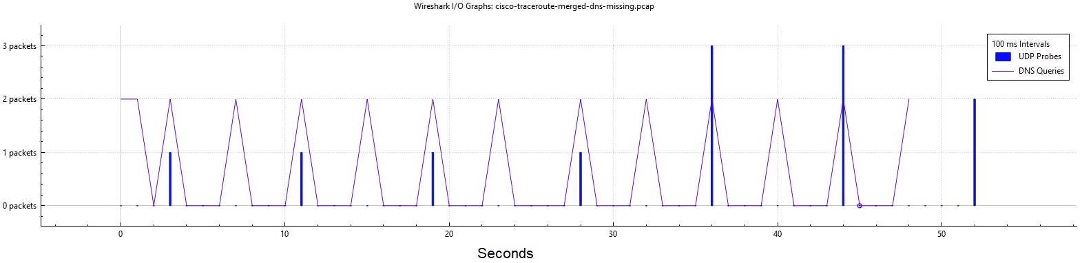
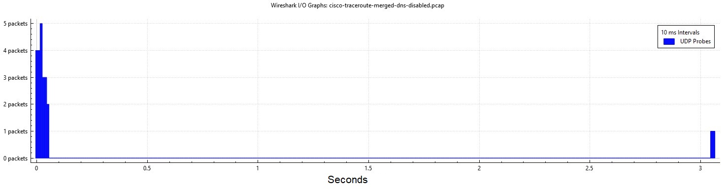
The first four packets are 8 seconds apart. The router requests PTR records for each IP.
It waits for those PTR queries.
12 probes takes about 50 seconds. I get the * in the results.
- cisco-traceroute-link-1-dns-missing.pcap
- cisco-traceroute-link-2-dns-missing.pcap
- cisco-traceroute-merged-dns-missing.pcap
Towards 8.8.8.8 with DNS enabled and working
Note
Exact same router.
The behavior changes when I connect the router to my lab network, and it gets a DHCP address and can reach the open Internet.
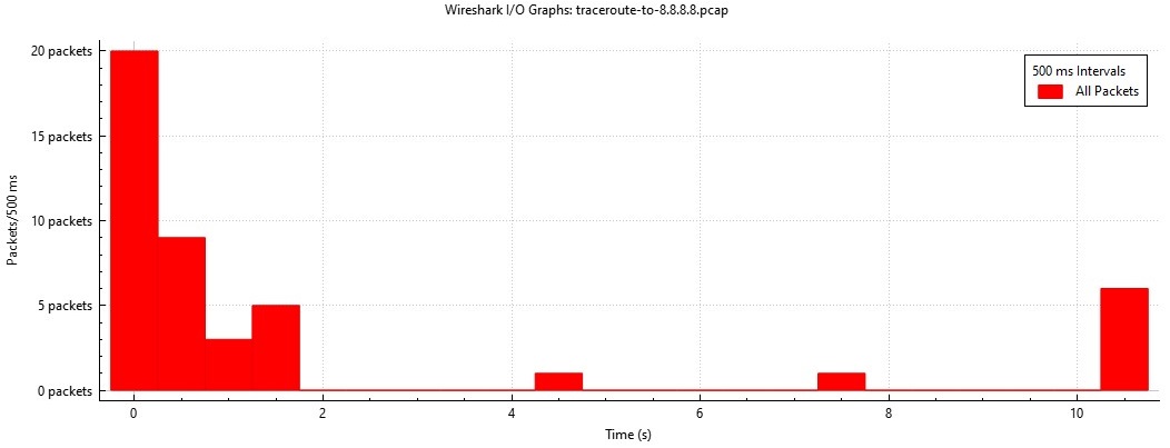
30+ probes complete in a little under 2 seconds. DNS is involved.
Disabling DNS lookups
The delay is reverse DNS: the captures show PTR queries for each newly seen hop address timing out between probes.
I added no ip domain lookup, it’s much faster but I still get the * in the results.
- cisco-traceroute-link-1-dns-disabled.pcap
- cisco-traceroute-link-2-dns-disabled.pcap
- cisco-traceroute-merged-dns-disabled.pcap
ICMP Type 3 Rate Limiting
IOS-XE defaults to 1 ICMP type 3 reply every 500 ms.
These replies are what traceroute needs to show a time result.
R1# show run all | i icmp rate-limit
ip icmp rate-limit unreachable 500
Show dropped replies
Looking at the captures, cisco-traceroute-merged-dns-missing.pcap and cisco-traceroute-merged-dns-disabled.pcap we do see the UDP probes arrive very close together.
If two probes come in too close together, the router will not reply.
Note
These drops will not show up with
debug icmp
R5# show ip icmp rate-limit

                           DF bit unreachables       All other unreachables
Interval (millisecond)     500                       500

Interface                  # DF bit unreachables     # All other unreachables
---------                  ---------------------     ------------------------
GigabitEthernet3           0                         0
GigabitEthernet4           0                         1
Loopback0                  0                         0
References
Use the Traceroute Command on Operating Systems - Cisco
IPv4
The 2004 Turing award was given to Vinton Cerf and Robert Kahn for the invention of TCP/IP.
Concepts from the 1974 IEEE paper:
- Gateways
- Separate different L2 networks
- TCP Port Multiplexing
- Connection Oriented
- Sequence Numbers
- Flow Control
- Retransmission
References
History of the Internet - Internet Society
IEN 54 - Internetwork Protocol Specification Version 4
A Protocol for Packet Network Intercommunication - IEEE Transactions on Communications
RFC 791: Internet Protocol | RFC Editor
IPv4 Addressing
Address ranges
| Range | Purpose | RFC | IPs |
|---|---|---|---|
0.0.0.0/8 | “This Network” | 791, 1122 | 16,777,216 |
10.0.0.0/8 | Private Use | 1918 | 16,777,216 |
127.0.0.0/8 | Loopback | 1122 | 16,777,216 |
172.16.0.0/12 | Private Use | 1918 | 1,048,576 |
169.254.0.0/16 | Automatic Addressing | 3927 | 65,536 |
192.0.2.0/24 | Documentation (TEST-NET-1) | 5737 | 256 |
192.168.0.0/16 | Private Use | 1918 | 65,536 |
198.51.100.0/24 | Documentation (TEST-NET-2) | 5737 | 256 |
203.0.113.0/24 | Documentation (TEST-NET-3) | 5737 | 256 |
224.0.0.0/4 | Multicast (Class D) | 5771 | 268,435,456 |
240.0.0.0/4 | Reserved / Experimental (Class E) | 1122 | 268,435,456 |
This Network
The 0.0.0.0 address literally means “when an app requests connectivity to 0.0.0.0, bind to every interface running IP and make it work”.
References
How Class E addresses solve for IP address exhaustion in GKE | Google Cloud Blog
IPv4 Packet Header
 0                   1                   2                   3
 0 1 2 3 4 5 6 7 8 9 0 1 2 3 4 5 6 7 8 9 0 1 2 3 4 5 6 7 8 9 0 1
┌───────┬───────┬───────────────┬───────────────────────────────┐
│Version│  IHL  │Type of Service│          Total Length         │
├───────┴───────┴───────────────┼─────┬─────────────────────────┤
│         Identification        │Flags│     Fragment Offset     │
├───────────────┬───────────────┼─────┴─────────────────────────┤
│  Time to Live │    Protocol   │        Header Checksum        │
├───────────────┴───────────────┴───────────────────────────────┤
│                         Source Address                        │
├───────────────────────────────────────────────────────────────┤
│                      Destination Address                      │
├───────────────────────────────────────────────┬───────────────┤
│                    Options                    │    Padding    │
└───────────────────────────────────────────────┴───────────────┘
Fields
| Field | Length | Description |
|---|---|---|
| Version | 4 bits | 0100 for IPv4, 0110 for IPv6 |
| IHL — Internet Header Length | 4 bits | Length of the header in 32-bit words. Minimum value is 5 (no options, no padding). |
| ToS — Type of Service | 8 bits | Quality of Service. Now used for DSCP. |
| Total Length | 16 bits | Total packet size in bytes (header + data). 16 bits × 8 = max packet size of 65,535 bytes. |
| Identification | 16 bits | Used to uniquely identify fragmented packets to add reassembly. |
| Flags | 3 bits | always 0, May Fragment, More Fragments |
| Fragment Offset | 13 bits | Where the fragment belongs. Units of 8 octets (64 bits). First fragment is set to 0. |
| TTL — Time to Live | 8 bits | Prevents routing loops. Each router decrements by 1; packet is discarded at 0. |
| Protocol | 8 bits | What the packet encapsulates, Ex: 1 = ICMP, 6 = TCP, 17 = UDP, 88 = EIGRP, 89 = OSPF. |
| Header Checksum | 16 bits | Covers the IP header only (not data). Recomputed at each device that processes the IP header. |
| Source Address | 32 bits | The SA — IP address of the sending host. |
| Destination Address | 32 bits | The DA — IP address of the destination host. |
| IP Options | Variable | Loose/Strict Source Routing, Record Route, Timestamp. Mostly unused, historical. |
| Padding | Variable | Ensures the header ends on a 32-bit boundary. |
Flags
  Flags:  3 bits

    Various Control Flags.

      Bit 0: reserved, must be zero
      Bit 1: (DF) 0 = May Fragment,  1 = Don't Fragment.
      Bit 2: (MF) 0 = Last Fragment, 1 = More Fragments.

          0   1   2
        +---+---+---+
        |   | D | M |
        | 0 | F | F |
        +---+---+---+
References
RFC 791: Internet Protocol | RFC Editor
IPv4 Address Planning
- Define the requirements
- Plan the ipv4 range
- Document the plan
Example standards
- Statically assign network infrastructure
- User devices are DHCP.
.1is the default gateway- Third Octet: The vlan ID.
10.0.150.0/24is vlan 150. - Forth Octet: Address Assignment type. 1 to 99 are static IPs, 100-200 are DHCP.
Figure out NAT
- How many IPs are needed?
- Do any devices need to be reachable from the outside?
Best practices
- Address internal hosts with RFC1918 addresses.
Recommended networks
| Purpose | Size |
|---|---|
| User Devices | /24 |
| Phones | /24 |
| Access Control | /24 |
| Video Conferencing | /24 |
| Point to Point Subnet | /31 |
| Loopback Subnet | /32 |
| Wireless APs | - |
References
IPv4 Interactive Map - bgp.tools
IPv4 Subnets
All IPv4 addresses are 32-bits, or four groups of eight.
We call each group of eight an octet.
An IPv4 Address in binary looks like this.
0000 0000 . 0000 0000 . 0000 0000 . 0000 0000
Some portion of those 32-bits are network bits N, and another portion are host bits H.
A /24 is 24 n-bits and 8 h-bits.
nnnn nnnn . nnnn nnnn . nnnn nnnn . hhhh hhhh
Since classful networking is dead, unless we are told the subnet mask, we cannot guess what the subnet size is from an IP
Terms
N-bit — Network Bit
- Identifies the network portion of a v4 address
H-bit — Host Bit
- Identifies the host portion of a v4 address
Via octet
We can subnet anywhere from /0 to /32. Even /31 is valid.
When a portion of the 32-bit space is used to make a subnet mask, we call these bits borrowed.
| Borrowed Bits | Binary | Decimal | Masks |
| –––––––|–––––| ––––| ––––––––––| | 0 | 00000000 | 0 | /0, /8, /16, /24 | | 1 | 10000000 | 128 | /1, /9, /17, /25 | | 2 | 11000000 | 192 | /2, /10, /18, /26 | | 3 | 11100000 | 224 | /3, /11, /19, /27 | | 4 | 11110000 | 240 | /4, /12, /20, /28 | | 5 | 11111000 | 248 | /5, /13, /21, /29 | | 6 | 11111100 | 252 | /6, /14, /22, /30 | | 7 | 11111110 | 254 | /7, /15, /23, /31 | | 8 | 11111111 | 255 | /8, /16, /24, /32 |
As powers of 2
Used to find subnets or the number of IPs.
For hosts use: \( 2^x - 2 \)
The default route, i.e. the whole Internet is /0.
| \( 2^x \) | Decimal | Subnet |
|---|---|---|
| 0 | /32 | 1 |
| 1 | /31 | 2 |
| 2 | /30 | 4 |
| 3 | /29 | 8 |
| 4 | /28 | 16 |
| 5 | /27 | 32 |
| 6 | /26 | 64 |
| 7 | /25 | 128 |
| 8 | /24 | 256 |
| 9 | /23 | 512 |
| 10 | /22 | 1,024 |
| 11 | /21 | 2,048 |
| 12 | /20 | 4,096 |
| 13 | /19 | 8,192 |
| 14 | /18 | 16,384 |
| 15 | /17 | 32,768 |
| 16 | /16 | 65,536 |
| 17 | /15 | 131,072 |
| 18 | /14 | 262,144 |
| 19 | /13 | 524,288 |
| 20 | /12 | 1,048,576 |
| 21 | /11 | 2,097,152 |
| 22 | /10 | 4,194,304 |
| 23 | /9 | 8,388,608 |
| 24 | /8 | 16,777,216 |
| 25 | /7 | 33,554,432 |
| 26 | /6 | 67,108,864 |
| 27 | /5 | 134,217,728 |
| 28 | /4 | 268,435,456 |
| 29 | /3 | 536,870,912 |
| 30 | /2 | 1,073,741,824 |
| 31 | /1 | 2,147,483,648 |
| 32 | /0 | 4,294,967,296 |
Config
A terrible and ancient way to load balance showing how subnet masks work.
!
! Use two /1s, impress your friends
!
! Useful to override your default network, I see wireguard uses this occasionally.
!
ip route 0.0.0.0   128.0.0.0 10.0.0.1
ip route 128.0.0.0 128.0.0.0 10.0.0.2
Subnetting with Fingers
I just memorize these sequences, ungainly, but works.
Decimal masks - 128, 192, 224, 240, 248, 252, 254, 255
Wildcard masks - 127, 63, 31, 15, 7, 3, 1, 0
Subnet Sizes (going up) - 256, 512, 1024, 2048
Subnet Sizes (going down) - 128, 64, 32, 16, 8, 4, 2, 1
Subnet examples
/24 is 256 IPs. Most gear complains if you use .0 or .256, so we say 254 usable hosts.
/30 is the 1990s way of addressing a point-to-point link, which wastes two IPs.
/31 is exactly two IPs. This is the best subnet for point-to-point links.
/32 is a single address. We call these host routes. 8.8.8.8/32 is Google’s DNS.
References
Using 31-Bit Prefixes on IPv4 Point-to-Point Links
Subnetting with the Box Method
For visual learners.
For a /24 network, thats 256 addresses, or … this box.
Start with A /24
Write the first IP in the top corner, the last IP in the bottom corner.
Cut in half (1)
Write the last number in the bottom corner, next number in the top corner.
Two /25 networks.
Cut in half (2)
- One
/25 - Two
/26networks.
Cut in half (3)
- One
/25 - Four
/27
Cut in half (4)
- One
/25 - Two
/27 - Four
/28
Subnetting with Binary
- A bit is
onoroff - A nibble is four bits
0000 - A byte is eight bits
0000 0000
Powers of 2: 1, 2, 4, 8, 16, 32, 64, 128, 256, 512, 1024, 2048
Examples
Start with a /24, eight free h bits, or values from 0 to 256.
0000 0000
100 hosts
A subnet needs 100 hosts, to represent that in binary, we’d need at least 7 bits, or 128.
A /24 would be too large, 256 IPs, remove a bit, and we get a /25.
10.0.0.0/25.
20 more hosts
We already spent the first portion of the address space, from 0 to 127.
0000 0000 is 0.
1000 0000 is 128.
How many bits to represent 20 hosts? at least 5, or \( 2^5 = 32-2 = 30 \)
So we start with 128, and use at least five bits.
1000 1000
References
Classful Networking
Never speak out loud “This is a class C address” unless you are in a 1990s movie.
Early Internet addressing (1980s) the IP itself indicated the subnet mask, by using the High Order bits. There were only three network sizes.
Internet Address starts with 0-127? You must have one network with 16 million hosts.
Internet Address starts with 128-191? You must have one network with 65 thousand hosts.
Internet Address starts with 192-223? You must have one network with 254 hosts.
We know now this was a terrible idea, but parts of it stay with us today.
/24(from class C) is a very popular prefix. This is said out loud as “A twenty four”./16(from class B) is a very popular prefix. This is said out loud as “A sixteen”.- All v4 multicast addresses still start with
1110
If someone gives you an IP, you can never guess its network without also being told the mask.
My personal favorite is 8.8.8.8/32 Google DNS it works by Anycast!
Classful networking, the RFC
RFC 791
Internet Protocol
Specification

  Addressing

    To provide for flexibility in assigning address to networks and
    allow for the  large number of small to intermediate sized networks
    the interpretation of the address field is coded to specify a small
    number of networks with a large number of host, a moderate number of
    networks with a moderate number of hosts, and a large number of
    networks with a small number of hosts.  In addition there is an
    escape code for extended addressing mode.

    Address Formats:

      High Order Bits   Format                           Class
      ---------------   -------------------------------  -----
            0            7 bits of net, 24 bits of host    a
            10          14 bits of net, 16 bits of host    b
            110         21 bits of net,  8 bits of host    c
            111         escape to extended addressing mode
ICMP
ICMP — Internet Control Message Protocol
ICMP is frequently used in network troubleshooting.
References
RFC 792: Internet Control Message Protocol | RFC Editor
IANA: Internet Control Message Protocol (ICMP) Parameters
Ping
ICMP — Internet Control Message Protocol
Ping tests IPv4 reachability and measures round-trip time using ICMP Echo messages.
Operation
┌──────┐    10.0.0.0/24    ┌──────┐
│  R1  ├───────────────────┤  R2  │
└──────┘.1               .2└──────┘
Verification
Sending the ping.
R1# ping 10.0.0.2
Sending 5, 100-byte ICMP Echos to 10.0.0.2, timeout is 2 seconds:
!!!!!
Success rate is 100 percent (5/5), round-trip min/avg/max = 1/1/2 ms
Counters on R1.
R1# show ip traffic | s ICMP
ICMP statistics:
  Rcvd: 0 format errors, 0 checksum errors, 0 redirects, 0 unreachable
        0 echo, 5 echo reply, 0 mask requests, 0 mask replies, 0 quench
        0 parameter, 0 timestamp, 0 timestamp replies, 0 info request, 0 other
        0 irdp solicitations, 0 irdp advertisements
        0 time exceeded, 0 info replies
  Sent: 0 redirects, 0 unreachable, 5 echo, 0 echo reply
        0 mask requests, 0 mask replies, 0 quench, 0 timestamp, 0 timestamp replies
        0 info reply, 0 time exceeded, 0 parameter problem
        0 irdp solicitations, 0 irdp advertisements
Counters on R2.
R2# show ip traffic | s ICMP statistics
ICMP statistics:
  Rcvd: 0 format errors, 0 checksum errors, 0 redirects, 0 unreachable
        5 echo, 0 echo reply, 0 mask requests, 0 mask replies, 0 quench
        0 parameter, 0 timestamp, 0 timestamp replies, 0 info request, 0 other
        0 irdp solicitations, 0 irdp advertisements
        0 time exceeded, 0 info replies
  Sent: 0 redirects, 0 unreachable, 0 echo, 5 echo reply
        0 mask requests, 0 mask replies, 0 quench, 0 timestamp, 0 timestamp replies
        0 info reply, 0 time exceeded, 0 parameter problem
        0 irdp solicitations, 0 irdp advertisements
As Hex
These can be pasted into an online packet decoder.
Echo request
52 54 00 40 e2 17 52 54 00 ff e7 79 08 00 45 00
00 64 00 00 00 00 ff 01 a7 96 0a 00 00 01 0a 00
00 02 08 00 95 aa 00 00 00 00 00 00 00 00 00 03
e8 9c ab cd ab cd ab cd ab cd ab cd ab cd ab cd
ab cd ab cd ab cd ab cd ab cd ab cd ab cd ab cd
ab cd ab cd ab cd ab cd ab cd ab cd ab cd ab cd
ab cd ab cd ab cd ab cd ab cd ab cd ab cd ab cd
ab cd
Echo Reply
52 54 00 ff e7 79 52 54 00 40 e2 17 08 00 45 00
00 64 00 00 00 00 ff 01 a7 96 0a 00 00 02 0a 00
00 01 00 00 9d aa 00 00 00 00 00 00 00 00 00 03
e8 9c ab cd ab cd ab cd ab cd ab cd ab cd ab cd
ab cd ab cd ab cd ab cd ab cd ab cd ab cd ab cd
ab cd ab cd ab cd ab cd ab cd ab cd ab cd ab cd
ab cd ab cd ab cd ab cd ab cd ab cd ab cd ab cd
ab cd
Packet Capture
References
RFC 792: Internet Control Message Protocol | RFC Editor
RFC 1122: Requirements for Internet Hosts | RFC Editor
ICMP Type 8 Echo Request
ICMP — Internet Control Message Protocol
The message preceding an ICMP Type 0 Echo Reply.
Every host MUST implement an ICMP Echo server function that receives Echo Requests and sends corresponding Echo Replies.
Source RFC 1122.
Header
 0                   1                   2                   3
 0 1 2 3 4 5 6 7 8 9 0 1 2 3 4 5 6 7 8 9 0 1 2 3 4 5 6 7 8 9 0 1
┌───────────────┬───────────────┬───────────────────────────────┐
│   Type = 8    │   Code = 0    │          Checksum             │
├───────────────┴───────────────┼───────────────────────────────┤
│          Identifier           │        Sequence Number        │
├───────────────────────────────┴───────────────────────────────┤
│                             Data                              │
└───────────────────────────────────────────────────────────────┘
Fields
| Field | Purpose |
|---|---|
| Identifier | Matches requests and replies to a ping process or session |
| Sequence Number | Matches each reply to a request and helps detect loss |
| Data | Payload that the receiver returns unchanged in the reply |
Ping sends Echo Requests to test IP reachability and measure round-trip time. A missing reply does not prove the destination is down; ICMP may be filtered or rate-limited.
References
RFC 792: Internet Control Message Protocol | RFC Editor
RFC 1122: Requirements for Internet Hosts | RFC Editor
IANA: Internet Control Message Protocol (ICMP) Parameters
ICMP Type 0 Echo Reply
ICMP — Internet Control Message Protocol
The response to an ICMP Type 8 Echo Request.
The data received in the echo message must be returned in the echo reply message.
Source RFC 792.
Responses will have
- Same identifier
- Same sequence number
- Same data
Header
 0                   1                   2                   3
 0 1 2 3 4 5 6 7 8 9 0 1 2 3 4 5 6 7 8 9 0 1 2 3 4 5 6 7 8 9 0 1
┌───────────────┬───────────────┬───────────────────────────────┐
│   Type = 0    │   Code = 0    │          Checksum             │
├───────────────┴───────────────┼───────────────────────────────┤
│          Identifier           │        Sequence Number        │
├───────────────────────────────┴───────────────────────────────┤
│                             Data                              │
└───────────────────────────────────────────────────────────────┘
References
RFC 792: Internet Control Message Protocol | RFC Editor
RFC 1122: Requirements for Internet Hosts | RFC Editor
IANA: Internet Control Message Protocol (ICMP) Parameters
ICMP Type 3 Destination Unreachable
ICMP — Internet Control Message Protocol
An ICMP Type 3 Destination Unreachable message explains why an IPv4 packet could not reach a network, host, protocol, or port.
If, in the destination host, the IP module cannot deliver the datagram because the indicated protocol module or process port is not active, the destination host may send a destination unreachable message to the source host.
Source RFC 792.
Header
 0                   1                   2                   3
 0 1 2 3 4 5 6 7 8 9 0 1 2 3 4 5 6 7 8 9 0 1 2 3 4 5 6 7 8 9 0 1
┌───────────────┬───────────────┬───────────────────────────────┐
│     Type      │     Code      │          Checksum             │
├───────────────┴───────────────┴───────────────────────────────┤
│                             unused                            │
├───────────────────────────────────────────────────────────────┤
│      Internet Header + 64 bits of Original Data Datagram      │
└───────────────────────────────────────────────────────────────┘
Codes
| Code | Name | Sent By | Meaning |
|---|---|---|---|
| 0 | Net Unreachable | Router | No route to destination network |
| 1 | Host Unreachable | Router | Route exists but host not responding |
| 2 | Protocol Unreachable | Destination host | IP protocol not supported |
| 3 | Port Unreachable | Destination host | UDP port not listening |
| 4 | Fragmentation Needed | Router | Packet too big, DF bit set |
| 9 | Net Administratively Prohibited | Router | ACL/policy blocks network |
| 10 | Host Administratively Prohibited | Router | ACL/policy blocks host |
| 13 | Communication Administratively Prohibited | Router or firewall | Administrative filtering blocks traffic |
References
RFC 792: Internet Control Message Protocol | RFC Editor
ICMP Type 11 Time Exceeded
ICMP — Internet Control Message Protocol
An ICMP Type 11 Time Exceeded message reports that a packet’s TTL expired in transit or that IPv4 fragment reassembly timed out.
If the gateway processing a datagram finds the time to live field is zero it must discard the datagram. The gateway may also notify the source host via the time exceeded message.
Source RFC 792.
Header
 0                   1                   2                   3
 0 1 2 3 4 5 6 7 8 9 0 1 2 3 4 5 6 7 8 9 0 1 2 3 4 5 6 7 8 9 0 1
┌───────────────┬───────────────┬───────────────────────────────┐
│     Type      │     Code      │          Checksum             │
├───────────────┴───────────────┴───────────────────────────────┤
│                             unused                            │
├───────────────────────────────────────────────────────────────┤
│  Internet Header + at least 64 bits of Original Datagram Data │
└───────────────────────────────────────────────────────────────┘
Codes
| Code | Name | Sent By | Meaning |
|---|---|---|---|
| 0 | Time to Live Exceeded in Transit | Router | TTL reached zero while the packet was being routed |
| 1 | Fragment Reassembly Time Exceeded | Destination host | All fragments did not arrive before the timer ended |
Traceroute
Traceroute sends probes with increasing TTL values.
Example
A sent Time-to-live exceeded message.
Received
Ethernet II, Src: 52:54:00:81:12:6f (52:54:00:81:12:6f), Dst: 52:54:00:d8:d7:63 (52:54:00:d8:d7:63)
Internet Protocol Version 4, Src: 10.1.12.2 (10.1.12.2), Dst: 10.0.0.1 (10.0.0.1)
Internet Control Message Protocol
    Type: Time-to-live exceeded (11)
    Code: 0 (Time to live exceeded in transit)
    Internet Protocol Version 4, Src: 10.0.0.1 (10.0.0.1), Dst: 10.0.0.5 (10.0.0.5)
    User Datagram Protocol, Src Port: 49435 (49435), Dst Port: mtrace (33435)
References
RFC 792: Internet Control Message Protocol | RFC Editor
RFC 1122: Requirements for Internet Hosts | RFC Editor
IANA: Internet Control Message Protocol (ICMP) Parameters
IPv6
Fundamentals
- 128 bits
- Global Scoped address tend to be Globally Unique
- Less need for NAT
- Fixed header length
- Optional, Option headers
- SLAAC
- Stateless host addressing
- Router advertising the subnet prefix
- Flow Labeling (for QoS)
- Routers cannot fragment packets
- Hosts perform MTU path discovery
- Hosts can have multiple addresses in multiple subnets
- Mobile IPv6 lets mobile nodes remain reachable
- No broadcast traffic
- No ARP
Bits
IPv6 address takes this form:
FFFF:FFFF:FFFF:FFFF:FFFF:FFFF:FFFF:FFFF
The groups are called hextets, as they are made with hex digits.
FFFF- 16 bits
FF- 8 bits
- One byte
F- 4 bits
- A nibble
Header format
RFCs really like groups of 32.
IPv6 addresses are 4 groups of 32.
                     1                   2                   3
 0 1 2 3 4 5 6 7 8 9 0 1 2 3 4 5 6 7 8 9 0 1 2 3 4 5 6 7 8 9 0 1
┌───────┬───────────────┬───────────────────────────────────────┐
│Version│ Traffic Class │           Flow Label                  │
├───────┴───────────────┴───────┬───────────────┬───────────────┤
│         Payload Length        │  Next Header  │   Hop Limit   │
├───────────────────────────────┴───────────────┴───────────────┤
│                                                               │
│                         Source Address                        │
│                                                               │
│                                                               │
├───────────────────────────────────────────────────────────────┤
│                                                               │
│                        Destination Address                    │
│                                                               │
│                                                               │
└───────────────────────────────────────────────────────────────┘
Address Blocks
| Address Block | Name | RFC | Notes |
|---|---|---|---|
::/128 | Unspecified | 4291 | Used on hosts when the IP isn’t known, means “bind to all addresses |
::1/128 | Loopback | 4291 | So hosts can talk to themselves |
::ffff:0:0/96 | IPv4 Mapped IPv6 | 4291 | Transition mechanism. Tells the app “I’m actually a v4 host” |
64:ff9b::/96 | WKP Translation | 6052 | NAT64 IPv4/IPv6 translation |
64:ff9b:1::/48 | Local Translation | 8215 | Local-use IPv4/IPv6 translation |
100::/64 | RTBH | 6666 | Discard prefix |
2000::/3 | Global Scope | 4291 | The current v6 Internet |
2001::/32 | Teredo | 4380 | Tunneling |
2001:db8::/32 | Documentation | 3849 | Intended for labs, books, documents |
2002::/16 | 6to4 | 3056 | Translation |
3fff::/20 | Documentation | 9637 | Intended for labs, books, documents. Bigger |
5f00::/16 | Segment Routing | 9602 | AKA, SRv6 |
fc00::/7 | ULA | 4193 | Reserved. Do not use |
fd00::/8 | ULA | 4193 | Supposed to be random subnet: |
fe80::/10 | Link Local | 4291 | L2 Only, not routeable |
ff00::/8 | Multicast | 4291 | No broadcasts in v6 |
IPv6 special address blocks
WKP — Well Known Prefix
This idea was from RFC 6052.
The idea was, you could look at a v6 address with 64 in the front and understand it had been translated.
These aren’t popular anymore
IPv4-Compatible IPv6 address
deprecated
RFC 4291 Section 2.5.5.1 provided this:
::10.0.0.1
These are only API addresses to represent to a IPv6 App, “this is actually a IPv4 host”
They don’t go anywhere.
IPv4-Mapped IPv6 address
RFC 4291 Section 2.5.5.2 provides this:
These are used in RFC 4038.
::FFFF:10.0.0.1
Intended for this flow where an IPv6 only app can work with IPv4 addresses.
┌──────────────────────────────────────────────┐
│ ┌──────────────────────────────────────────┐ │
│ │                                          │ │
│ │          IPv6-only applications          │ │
│ │                                          │ │
│ └────────────────────┬─────────────────────┘ │
│                      │                       │
│ ┌────────────────────┴─────────────────────┐ │
│ │                                          │ │
│ │   TCP / UDP / others (SCTP, DCCP, etc.)  │ │
│ │                                          │ │
│ └─────────────────┬────────┬───────────────┘ │
│    IPv4-mapped    │        │    IPv6         │
│  IPv6 addresses   │        │   addresses     │
│ ┌─────────────────┴──┐ ┌───┴───────────────┐ │
│ │        IPv4        │ │       IPv6        │ │
│ └────────────┬───────┘ └───────┬───────────┘ │
│   IPv4       │                 │             │
│   addresses  │                 │             │
└───────────── │ ─────────────── │ ────────────┘
               │                 │
          IPv4 packets      IPv6 packets
References
RFC 2460 - Internet Protocol, Version 6 (IPv6)
Cisco Live - IPv6:: It’s Happening - Nathan Sherrard - BRKIPV-2191
Cisco Live - Deploying IPv6 Routing Protocols - Peter Palúch - BRKIPV-2418
RFC 9099: Operational Security Considerations for IPv6 Networks
IPv6 Subnetting
Not really used by individual sites, but if you get a block from a RIR, this is how to subnet it.
In the US ARIN handles requests for v6 space.
Could be useful to work with NPTv6
Blessed subnets
The easy v6 networks to subnet fall on hex digit boundaries of /4.
For these, see this chart.
/40
You’re given 3fff::/20, make some /40 networks.
A /40 is two hextets, and two hex digits worth of bits.
3fff:0:0000::/403fff:0:0100::/403fff:0:0200::/403fff:0:0300::/403fff:0:0400::/403fff:0:0500::/40
which becomes
3fff:0::/403fff:0:100::/403fff:0:200::/403fff:0:300::/403fff:0:400::/403fff:0:500::/40
/44
You’re given 3fff::/20, make some /44 networks.
A /44 is two hextets, and three hex digits worth of bits.
3fff:0:0000::/443fff:0:0010::/443fff:0:0020::/443fff:0:0030::/443fff:0:0040::/443fff:0:0050::/44
which becomes
3fff:0::/443fff:0:10::/443fff:0:20::/443fff:0:30::/443fff:0:40::/443fff:0:50::/44
/48
You’re given 3fff::/20, make some /48 networks.
A /48 is three hextets, worth of bits.
3fff:0:0::/483fff:0:1::/483fff:0:2::/483fff:0:3::/483fff:0:4::/48
Cursed subnets
What if instead, we try and subnet, inside a hex digit?
First, we’d have to know what every hex digit is in binary.
| Hex | Binary |
|---|---|
| 0 | 0000 |
| 1 | 0001 |
| 2 | 0010 |
| 3 | 0011 |
| 4 | 0100 |
| 5 | 0101 |
| 6 | 0110 |
| 7 | 0111 |
| 8 | 1000 |
| 9 | 1001 |
| A | 1010 |
| B | 1011 |
| C | 1100 |
| D | 1101 |
| E | 1110 |
| F | 1111 |
Then we’d want to figure out where the boundaries are for bits borrowed:
| Bits Borrowed | Boundaries |
|---|---|
| 1 bit | 0, 8 |
| 2 bits | 0, 4, 8, C |
| 3 bits | 0, 2, 4, 6, 8, A, C, E |
/49
You’re given 3fff::/20, make some /49 networks.
A /49 is three hextets, plus one binary bit.
3fff:0:0:0::/493fff:0:0:8000::/493fff:0:1:0::/493fff:0:1:8000::/493fff:0:2:0000::/49
/50
You’re given 3fff::/20, make some /50 networks.
A /50 is three hextets, plus two binary bits.
3fff:0:0:0::/503fff:0:0:4000::/503fff:0:0:8000::/503fff:0:0:C000::/503fff:0:1:0000::/50
/51
You’re given 3fff::/20, make some /51 networks.
A /51 is three hextets, plus three binary bits.
3fff:0:0:0::/513fff:0:0:2000::/513fff:0:0:4000::/513fff:0:0:6000::/513fff:0:0:8000::/51
References
IPv6 Hextet Boundaries
For any of these, to subnet them, just change the final hex digit.
Groups of 64
/64   FFFF:FFFF:FFFF:FFFF::
/128  FFFF:FFFF:FFFF:FFFF:FFFF:FFFF:FFFF:FFFF
Groups of 32
/32   FFFF:FFFF::
/64   FFFF:FFFF:FFFF:FFFF::
/96   FFFF:FFFF:FFFF:FFFF:FFFF:FFFF::
/128  FFFF:FFFF:FFFF:FFFF:FFFF:FFFF:FFFF:FFFF
As groups of 16
/16   FFFF::
/32   FFFF:FFFF::
/48   FFFF:FFFF:FFFF::
/64   FFFF:FFFF:FFFF:FFFF::
/80   FFFF:FFFF:FFFF:FFFF:FFFF::
/96   FFFF:FFFF:FFFF:FFFF:FFFF:FFFF::
/112  FFFF:FFFF:FFFF:FFFF:FFFF:FFFF:FFFF::
/128  FFFF:FFFF:FFFF:FFFF:FFFF:FFFF:FFFF:FFFF
Groups of 8
/8    FF::
/16   FFFF::
/24   FFFF:FF::
/32   FFFF:FFFF::
/40   FFFF:FFFF:FF::
/48   FFFF:FFFF:FFFF::
/56   FFFF:FFFF:FFFF:FF::
/64   FFFF:FFFF:FFFF:FFFF::
/72   FFFF:FFFF:FFFF:FFFF:FF::
/80   FFFF:FFFF:FFFF:FFFF:FFFF::
/88   FFFF:FFFF:FFFF:FFFF:FFFF:FF::
/96   FFFF:FFFF:FFFF:FFFF:FFFF:FFFF::
/104  FFFF:FFFF:FFFF:FFFF:FFFF:FFFF:FF::
/112  FFFF:FFFF:FFFF:FFFF:FFFF:FFFF:FFFF::
/120  FFFF:FFFF:FFFF:FFFF:FFFF:FFFF:FFFF:FF::
/128  FFFF:FFFF:FFFF:FFFF:FFFF:FFFF:FFFF:FFFF
Groups of 4
/4    F::
/8    FF::
/12   FFF::
/16   FFFF::
/20   FFFF:F::
/24   FFFF:FF::
/28   FFFF:FFF::
/32   FFFF:FFFF::
/36   FFFF:FFFF:F::
/40   FFFF:FFFF:FF::
/44   FFFF:FFFF:FFF::
/48   FFFF:FFFF:FFFF::
/52   FFFF:FFFF:FFFF:F::
/56   FFFF:FFFF:FFFF:FF::
/60   FFFF:FFFF:FFFF:FFF::
/64   FFFF:FFFF:FFFF:FFFF::
/68   FFFF:FFFF:FFFF:FFFF:F::
/72   FFFF:FFFF:FFFF:FFFF:FF::
/76   FFFF:FFFF:FFFF:FFFF:FFF::
/80   FFFF:FFFF:FFFF:FFFF:FFFF::
/84   FFFF:FFFF:FFFF:FFFF:FFFF:F::
/88   FFFF:FFFF:FFFF:FFFF:FFFF:FF::
/92   FFFF:FFFF:FFFF:FFFF:FFFF:FFF::
/96   FFFF:FFFF:FFFF:FFFF:FFFF:FFFF::
/100  FFFF:FFFF:FFFF:FFFF:FFFF:FFFF:F::
/104  FFFF:FFFF:FFFF:FFFF:FFFF:FFFF:FF::
/108  FFFF:FFFF:FFFF:FFFF:FFFF:FFFF:FFF::
/112  FFFF:FFFF:FFFF:FFFF:FFFF:FFFF:FFFF::
/116  FFFF:FFFF:FFFF:FFFF:FFFF:FFFF:FFFF:F::
/120  FFFF:FFFF:FFFF:FFFF:FFFF:FFFF:FFFF:FF::
/124  FFFF:FFFF:FFFF:FFFF:FFFF:FFFF:FFFF:FFF::
/128  FFFF:FFFF:FFFF:FFFF:FFFF:FFFF:FFFF:FFFF
IPv6 Network Address Planning
Terms
PIN — Place In Network
- Use v6 nibbles to tell you what the subnet does
Per the RFC
RFC 3587 contains the current recommendations for v6 site design.
“Get a /48 from your RIR.”
│ 3 │     45 bits         │  16 bits  │       64 bits              │
├───┼─────────────────────┼───────────┼────────────────────────────┤
│001│global routing prefix│ subnet ID │       interface ID         │
└───┴─────────────────────┴───────────┴────────────────────────────┘
Cisco’s Guidance
PIN
Use the hex nibbles to encode things.
| Value | Purpose |
|---|---|
| 0 | Reserved |
| 2 | Infrastructure |
| 4 | Desktop (wired) |
| 6 | Wireless (corp) |
| 8 | Guest Wi-Fi |
| A | Lab |
| C | Building DC |
| E | DMZ |
| F | Reserved |
| Odd | Future Use |
Desktop subnet 200   2001:0db8:729c:4200::/52
Desktop subnet 300   2001:0db8:729c:4300::/52
Lab     subnet 004   2001:0db8:729c:A004::/52
Lab     subnet 006   2001:0db8:729c:A006::/52
BGP
Common subnets found in v6 BGP global table.
| Prefix | Usage |
|---|---|
| /24 – /29 | Large ISP/provider aggregates |
| /32 | Standard ISP/LIR allocation |
| /36 – /44 | Sub-allocations, multi-site orgs |
| /48 | End-site (dominant) |
| /64 | One subnet |
| /127 | Used on p2p links to prevent attacks |
Found in the APNIC BGP in 2025 pdf.
If a /24 is the minimum accepted route prefix size in IPv4, what is the comparable size in IPv6?
There appears to be no common consensus position here. The default action many for network operators appears to have no minimum size filter at all. In theory, that would imply that a /128 route object would be accepted across the entire IPv6 DFZ. A more pragmatic observation is that a /32 would be assuredly accepted by all networks, and it appears that many network operators believe that a /48 is also generally accepted. Given that a /48 is the most common prefix size in today’s IPv6 network, this view appears to be widespread. We also see prefixes smaller in size than a /48 in the routing table with /49, /52, /56 and /64 prefixes present in the IPv6 BGP routing table. 0.7% all advertised prefixes are more specific than a /48.
Site planning
Since each site gets its own /48, there are 65k networks to work with.
References
RFC 3587: IPv6 Global Unicast Address Format | RFC Editor
How to Request IPv6 Address Space from ARIN
IPv6 Link Local Addressing
These are on-link
Always takes the form fe80::/64
My computer: fe80::2215:3789:d6f8:a04f
References
RFC 4862: IPv6 Stateless Address Autoconfiguration | RFC Editor
Cisco - Understand the IPv6 Link-Local Address
IPv6 Unique Local Addressing
Sort of but not quite equivalent to RFC 1918.
- Any site can generate a ULA and start using it
- Not meant to go over the global v6 Internet
Terms
ULA — Unique Local Address
- Globally unique via randomness
- Take the form,
fdxx:xxxx:xxxx::/48 - Five bytes or 40 bits of entropy
Site prefixes
\( 2^{40} = 1{,}099{,}511{,}627{,}776 \)
Approximately 1 trillion unique site prefixes.
Site prefix generation
Each site should generate a unique ULA using a RNG.
Random.org - Five Random Bytes
fdxx:xxxx:xxxx::/48
Examples
Don’t copy my examples … ☹️
fd1a:b22c:c764::/48fd39:42fb:f7a7::/48fdb1:bf6c:f270::/48
References
RFC 4193: Unique Local IPv6 Unicast Addresses | RFC Editor
ICMPv6
Required for IPv6 to work correctly.
Header
 0                   1                   2                   3
 0 1 2 3 4 5 6 7 8 9 0 1 2 3 4 5 6 7 8 9 0 1 2 3 4 5 6 7 8 9 0 1
┌───────────────┬───────────────┬───────────────────────────────┐
│     Type      │     Code      │          Checksum             │
├───────────────┴───────────────┴───────────────────────────────┤
│                                                               │
│                         Message Body                          │
│                                                               │
Error Messages
| Type | Purpose |
|---|---|
| 1 | Destination Unreachable |
| 2 | Packet Too Big |
| 3 | Time Exceeded |
| 4 | Parameter Problem |
Informational Messages
| Type | Purpose |
|---|---|
| 128 | Echo Request |
| 129 | Echo Reply |
References
RFC 4443 - Internet Control Message Protocol (ICMPv6) for IPv6
IPv6 Neighbor Discovery
RA messages are sent with ICMPv6. These can carry options, so they’ve been extended to carry RDNSS information.
The router can say “Here is the DNS info”.
Terms
ND — Neighbor Discoery
RA — Router Advertisement
In v6, routers can just advertise the prefix of the attached subnet and options like RDNSS.
RDNSS — Recursive DNS Server
DAD — Duplicate Address Detection
Functions
- SLAAC
- DAD
- Prefix Discoery
- Parameter Discovery
- Address Resolution
- Router Discovery
- Next-Hop Determination
- Neighbor Unreachability Detection
- Redirects
RDNS server option
RFC 8106: IPv6 Router Advertisement Options for DNS Configuration
 0                   1                   2                   3
 0 1 2 3 4 5 6 7 8 9 0 1 2 3 4 5 6 7 8 9 0 1 2 3 4 5 6 7 8 9 0 1
┌───────────────┬───────────────┬───────────────────────────────┐
│     Type      │     Length    │           Reserved            │
├───────────────┴───────────────┴───────────────────────────────┤
│                           Lifetime                            │
├───────────────────────────────────────────────────────────────┤
│                      Addresses of IPv6                        │
│                    Recursive DNS Servers                      │
└───────────────────────────────────────────────────────────────┘
References
RFC 4861: Neighbor Discovery for IP version 6 (IPv6) | RFC Editor
RFC 8106: IPv6 Router Advertisement Options for DNS Configuration | RFC Editor
IPv6 ND Router Advertisements
Header
RFC 4861: Neighbor Discovery for IPv6
 0                   1                   2                   3
 0 1 2 3 4 5 6 7 8 9 0 1 2 3 4 5 6 7 8 9 0 1 2 3 4 5 6 7 8 9 0 1
┌───────────────┬───────────────┬───────────────────────────────┐
│     Type      │     Code      │          Checksum             │
├───────────────┼─┬─┬───────────┼───────────────────────────────┤
│ Cur Hop Limit │M│O│  Reserved │       Router Lifetime         │
├───────────────┴─┴─┴───────────┴───────────────────────────────┤
│                         Reachable Time                        │
├───────────────────────────────────────────────────────────────┤
│                          Retrans Timer                        │
├───────────────────────────────────────────────────────────────┘
│   Options ...
└───────────────────────
RDNS server option
RFC 8106: IPv6 Router Advertisement Options for DNS Configuration
 0                   1                   2                   3
 0 1 2 3 4 5 6 7 8 9 0 1 2 3 4 5 6 7 8 9 0 1 2 3 4 5 6 7 8 9 0 1
┌───────────────┬───────────────┬───────────────────────────────┐
│     Type      │     Length    │           Reserved            │
├───────────────┴───────────────┴───────────────────────────────┤
│                           Lifetime                            │
├───────────────────────────────────────────────────────────────┤
│                      Addresses of IPv6                        │
│                    Recursive DNS Servers                      │
└───────────────────────────────────────────────────────────────┘
Packet capture
Taken from my home router 13-July-2026, I’ve modified the IPs.
Frame 46: Packet, 174 bytes on wire (1392 bits), 174 bytes captured (1392 bits) on interface <removed>
Ethernet II, Src: Routerboardc_ef:69:14 (48:a9:8a:ef:69:14), Dst: IPv6mcast_01 (33:33:00:00:00:01)
Internet Protocol Version 6, Src: fe80::4aa9:8aff:feef:6914, Dst: ff02::1
Internet Control Message Protocol v6
    Type: Router Advertisement (134)
    Code: 0
    Checksum: 0xa34c [correct]
    [Checksum Status: Good]
    Cur hop limit: 0
    Flags: 0x00, Prf (Default Router Preference): Medium
    Router lifetime (s): 1800
    Reachable time (ms): 0
    Retrans timer (ms): 0
    ICMPv6 Option (Source link-layer address : 48:a9:8a:ef:69:14)
    ICMPv6 Option (Recursive DNS Server 2001:db8:12:15::6 2001:db8:12:15::7)
        Type: Recursive DNS Server (25)
        Length: 5 (40 bytes)
        Reserved
        Lifetime: 1800 (30 minutes)
        Recursive DNS Servers: 2001:db8:12:15::6
        Recursive DNS Servers: 2001:db8:12:15::7
    ICMPv6 Option (Recursive DNS Server fe80::4aa9:8aff:feef:6914)
        Type: Recursive DNS Server (25)
        Length: 3 (24 bytes)
        Reserved
        Lifetime: RDNSS address MUST no longer be used (0) (0 seconds)
        Recursive DNS Servers: fe80::4aa9:8aff:feef:6914
    ICMPv6 Option (Prefix information : 2001:db8:12:15::/64)
        Type: Prefix information (3)
        Length: 4 (32 bytes)
        Prefix Length: 64
        Flag: 0xc0, On-link Flag (L), Autonomous Address Configuration Flag (A)
            1... .... = On-link Flag (L): Set
            .1.. .... = Autonomous Address Configuration Flag (A): Set
            ..0. .... = Router Address Flag (R): Not set
            ...0 .... = DHCPv6-PD Preferred Flag (P): Not set
            .... 0000 = Reserved: 0
        Valid Lifetime: 2592000 (30 days)
        Preferred Lifetime: 604800 (7 days)
        Reserved
        Prefix: 2001:db8:12:15::
Wireshark
BPF:ip6 protochain 58
References
RFC 4861: Neighbor Discovery for IP version 6 (IPv6) | RFC Editor
RFC 8106: IPv6 Router Advertisement Options for DNS Configuration | RFC Editor
IPv4 to IPV6 Migration Strategies
Dual-stack
- AKA, Native Mode
- AKA, Ships in the Night
- Both at the same time
- Twice the administrative overhead
Tunneling
- Encapsulate the IPv6 packets
- Into IPv4
- Send
Translation
- Make the IPv6 packets back into IPv4 packets.
ISATAP — Intra-Site Automatic Tunneling Addressing
Hybrid Model
- Uses ISATAP
Service Blocks
- Combing tunnels with dual-stack.
Native mode
Both stacks are running on clients. The clients request A and AAAA records near simultaneously.
Whichever DNS records return first decides if the next set of flows are v4 or v6.
This strategy is called “Happy Eyeballs” after the RFC. Do not punish users by “preferring” one protocol or another.
Do whatever is fastest.
Tunneling
- Reduces MTU by 20 bytes.
- The preferred tunnel is GRE.
Automatic tunnels
6to4
- Uses
2002::/16
6RD
- The ISP uses its own addressing.
ISATAP — Intra-site Automatic Tunnel Addressing Protocol
- Uses these 32 bits to denotes ISATAP
0000:5EFE
Translation
- Much like NAT
DNS64 and NAT64
DNS64
- DNS creates synthetic AAAA records, so a v4 client can connect to a v6 service.
NAT64
- A router translates IPv6 traffic to IPv4 traffic.
References
Happy Eyeballs Version 2: Better Connectivity Using Concurrency
Connection of IPv6 Domains via IPv4 Clouds
Framework for IPv4/IPv6 Translation
ISATAP
- Deprecated
- Packet-in-packet technology
- Mostly historical
- Used within one site, not an Internet Technology
- “v6 islands within a v4 ocean”
- Treats the v4 network as NBMA
- ISATAP devices must be dual stacked
- Adds 20-bytes of overhead
- Works as long as v4 routing works
- Stateless
Theory
Use v4 connectivity to emulate a NBMA network. Wrap the v6 packet inside v4.
┌───────────┬───────────┐
│ v6-packet │ v4-header │ ───────►
└───────────┴───────────┘
Router ISATAP
         v6 only             v4 only             v6 only
         ┌─────┐       ┌─────────────────┐       ┌─────┐
         ▼     ▼       ▼                 ▼       ▼     ▼
┌────────┐     ┌───────┐     ┌─────┐     ┌───────┐     ┌────────┐
│client-1│     │   R1  │     │ R2  │     │   R3  │     │client-2│
│   v6   ├─────┤ v4/v6 ├─────┤  v4 ├─────┤ v4/v6 ├─────┤   v6   │
└────────┘     └───────┘     └─────┘     └───────┘     └────────┘
                     ISATAP           ISATAP
                      Interface        Interface
Client ISATAP
                           v4 only
               ┌─────────────────────────────┐
               ▼                             ▼
┌────────┐     ┌─────┐     ┌─────┐     ┌─────┐     ┌────────┐
│client-1│     │ R1  │     │ R2  │     │ R3  │     │client-2│
│ v4/v6  ├─────┤  v4 ├─────┤  v4 ├─────┤  v4 ├─────┤  v4/v6 │
└────────┘     └─────┘     └─────┘     └─────┘     └────────┘
      ISATAP                                     ISATAP
       Interface                                  Interface
ISATAP interface in v6
All ISATAP interfaces look like this. The giveaway is 0000:5EFE in the host portion.
If a router sees a v6 destination that looks like this, it’s an ISATAP packet.
           64 bits                32 bits        32 bits
┌─────────────────────────────┬──────────────┬──────────────┐
│       Global Unicast        │  0000:5EFE   │ IPv4 Address │
│           Prefix            │              │on ISATAP Link│
└─────────────────────────────┴──────────────┴──────────────┘
Terms
PRL — Potential Router List
- Routers that could perform ISATAP
ISATAP Interface
- Dual-stack
- Has the v6 IP
ISATAP v4 Address
- NBMA address
- How to reach this device via ISATAP
ISATAP v6 Address
- End-to-end v6 address
- Must embed the v4 address
References
RFC 5214: Intra-Site Automatic Tunnel Addressing Protocol (ISATAP)
IP Routing Configuration Guide - ISATAP Tunnel Support for IPv6 Support - Cisco
6RD
6to4
- The base standard
- Requires a specific prefix
6RD
- The current standard
- Allows any global prefix
RG — Router Gateway
- The CPE the ISP provides to connect to their network
BNG — Broadband Network Gateway
- This is the Customer aggregation node
- Aggregate thousands of connections
NMS — Network Management System
- Provides a place to see and configure the network
AAA — Authentication, Authorization, Accounting
- This is how the ISP controls who can access the network
- Controls QoS Deployments
BR
- Terminates the 6RD tunnels
- AKA, Border Relay
What does 6RD solve?
“We can’t deploy v6, because our BNG does (put-feature-here) and we need that!
This way, the customer gets dual stack without the ISP needing to upgrade a legacy deployment.
The four things required to setup
- IPv4 Common Prefix: - The high order bits every CE has in common for their v4 deployments.
If every customer was given an IP on the 10.0.0.0/24 network, the bits they would have in common is /24.
- 6RD Prefix: The v6 bits for the 6rd domain.
- 6RD PrefixLen: The length of the prefix for the 6rd domain.
- 6RD BR v4 Address: The Access Network v4 address for the BR.
(there is a neat way to derive the 6rd prefix, refer to Cisco’s IOS-XE manual, that’s closest to how it’s done.)
Sample config (from Cisco’s PDF)
!
! This BR is reachable via the loopback.
!
interface Loopback0
ip address 10.1.1.1 255.255.255.0
!
interface Tunnel0
 tunnel source Loopback0
 tunnel mode ipv6ip 6rd
 tunnel 6rd ipv4 prefix-len 8
 tunnel 6rd prefix 2011:1001:100:/40
 ipv6 address 2011:1001:101:101::/128 anycast
!
ipv6 route 2011:1001:100::/40 Tunnel0
ipv6 route 2011:1001:101:101::/64 Null0
!
! Simple and Easy to setup!
!
#show tunnel 6rd
Interface Tunnel0:
 Tunnel Source: 10.1.1.1
 6RD: Operational, V6 Prefix: 2011:1001:100:/40
 V4 Prefix, Length: 8, Value: 10.0.0.0
 V4 Suffix, Length: 0, Value: 0.0.0.0
 General Prefix: 2011:1001:1
References
RFC 3056: Connection of IPv6 Domains via IPv4 Clouds | RFC Editor
RFC 5969: IPv6 Rapid Deployment on IPv4 Infrastructures (6rd) – Protocol Specification | RFC Editor
APNIC Conference | 6RD Enabling IPv6 Customers on an IPv4-only Network
NAT64
Allows v6 only clients access to v4 only services.
Requires:
- DNS64 Server to translate an A record to a synthetic AAAA record
- NAT64 Router to keep state
- Upstream DNS to respond with an A record, to the DNS64 server
- Stateful Prefix
sequenceDiagram
    participant PC as Host<br/>v6 only
    participant DNS64 as Server<br/>DNS64
    participant DNS4 as Server<br/>DNS4
    participant R1 as Router<br/>NAT64
    Participant Web as Web Server<br/>v4 only

    PC    ->>   DNS64: Request AAAA
    DNS64 ->>   DNS4: Request A
    DNS4  -->>  DNS64: Answer with A
    DNS64 -->>  PC: Translate to Synthetic AAAA
    PC    ->>   R1: Send with v6 prefix
    R1    ->>   Web: Translate to v4
    Web   -->>  R1: Respond with v4
    R1    -->>  PC: Check Translations<br/>Reply with v6
Config
ipv6 unicast-routing
!
! Define NAT64 Prefix
!
nat64 prefix stateful 2001:DB8:0:64::/96
!
! Create NAT64 pool
!
nat64 v4 pool DHCP_POOL64 10.0.0.100 10.0.0.200
!
! Create ACL for NAT64 Clients
!
ipv6 access-list ACL_NAT64_CLIENTS
  permit ipv6 2001:db8:1::/48 any
!
! Match v6 clients to the v4 pool
!
nat64 v6v4 list ACL_NAT64_CLIENTS pool DHCP_POOL64 overload
!
! Enable on v6 network
!
interface GigabitEthernet3
 ipv6 address 2001:db8:1::1/64
 nat64 enable
!
! Enable on v4 network
!
interface GigabitEthernet1
 ip address 10.0.0.1 255.255.255.0
 nat64 enable
DNS64
apk update apk add unbound apk add bind-tools rc-update add unbound default
DNS64:~# cat /etc/unbound/unbound.conf
server:
    interface: 0.0.0.0
    interface: ::0
    access-control: 0.0.0.0/0 allow
    access-control: ::/0 allow
    do-ip4: yes
    do-ip6: yes
    do-udp: yes
    do-tcp: yes
    module-config: "dns64 iterator"
    # Do not use the Well-Known-Prefix, it breaks with private v4 addresses.
    # See https://datatracker.ietf.org/doc/html/rfc6052#section-3.4
    dns64-prefix: 2001:db8:0:64::/96

forward-zone:
        name: "."
        # A different upstream server, that returns only an A record.
        forward-addr:  2001:db8:1::6
DNS4
Installing Apps
apk update
apk add unbound
apk add bind-tools
rc-update add unbound default
DNS4:~$ cat /etc/unbound/unbound.conf
server:
    interface: 0.0.0.0
    interface: ::0
    access-control: 0.0.0.0/0 allow
    access-control: ::/0 allow
    do-ip4: yes
    do-ip6: yes
    do-udp: yes
    do-tcp: yes
    local-data: "64lab.example.com. A 10.0.0.20"
Verification
R1# show nat64 translations

Proto  Original IPv4         Translated IPv4
       Translated IPv6       Original IPv6
----------------------------------------------------------------------------

icmp   10.0.0.20:2           [2001:db8:0:64::a00:14]:2
       10.0.0.100:2          [2001:db8:1:0:5054:ff:fe11:d8ec]:2

Total number of translations: 1
The WKP (Well Known Prefix) will not work toward RFC1918 addresses. You must configure a different /96.
References
RFC 6052: IPv6 Addressing of IPv4/IPv6 Translators | RFC Editor
RFC 4291: IP Version 6 Addressing Architecture | RFC Editor
RFC 2464: Transmission of IPv6 Packets over Ethernet Networks
Stateless NAT64
Uses one v4 address for each v6 address.
Prefix Embedding
From RFC 6052
    ┌──────────────────────────────────────────────────────────────────┐
 PL │0-----------------32--40--48--56--64--72--80--88--96--104-112-120-│
    ├──────────────────┬───────────────┬───┬───────────────────────────┤
/32 │      prefix      │         v4(32)│ u │                 suffix    │
    ├──────────────────┴───┬───────────┼───┼───┬───────────────────────┤
/40 │      prefix          │     v4(24)│ u │(8)│             suffix    │
    ├──────────────────────┴───┬───────┼───┼───┴───┬───────────────────┤
/48 │      prefix              │ v4(16)│ u │ v4(16)│         suffix    │
    ├──────────────────────────┴───┬───┼───┼───────┴───┬───────────────┤
/56 │      prefix                  │(8)│ u │ v4(24)    │     suffix    │
    ├──────────────────────────────┴───┼───┼───────────┴───┬───────────┤
/64 │      prefix                      │ u │ v4(32)        │ suffix    │
    ├──────────────────────────────────┴───┴───────────┬───┴───────────┤
/96 │      prefix                                      │    v4(32)     │
    └──────────────────────────────────────────────────┴───────────────┘
Supported Prefixes
- /32
- /40
- /48
- /56
- /64
- /96
References
RFC 6052: IPv6 Addressing of IPv4/IPv6 Translators | RFC Editor
RFC 7915: IP/ICMP Translation Algorithm | RFC Editor
Cisco - IP Addressing Configuration Guide, IOS-XE 17.x - Stateless Network Address Translation 64
Ethernet CSMA/CD
Is used when the link is half-duplex. For full-duplex links CDMA/CD isn’t used.
This standard provides for two modes of operation of the MAC sublayer:
a) In half duplex mode, stations contend for the use of the physical medium, using the CSMA/CD algorithms specified.
Bidirectional communication is accomplished by rapid exchange of frames, rather than full duplex operation.
Half duplex operation is possible on all supported media; it is required on those media that are incapable of supporting simultaneous transmission and reception without interference, for example, 10BASE2 and 100BASE-T4.
b) The full duplex mode of operation can be used when all of the following are true:
The physical medium is capable of supporting simultaneous transmission and reception without interference (e.g., 10BASE-T, 10BASE-FL, and 100BASE-TX/FX).
There are exactly two stations on the LAN. This allows the physical medium to be treated as a full duplex point-to-point link between the stations. Since there is no contention for use of a shared medium, the multiple access (i.e., CSMA/CD) algorithms are unnecessary.
Both stations on the LAN are capable of and have been configured to use full duplex operation.
Source - IEEE 802.3-2022 - Section 4.1.1 Media Access Control, Functional model of the MAC method, Overview
References
802.3-2022 - IEEE Standard for Ethernet
10G Ethernet
Terms
WAN PHY
These can operate with SONET/SDH at STS-192c.
GPON
Gigabit Passive Optical Network. Passive because none of the intermediate gear is powered.
| Media Type | Wavelength | Medium | Distance | IEEE Spec | Other Description |
|---|---|---|---|---|---|
| SFP+ | Direct Attach | ≤ 10 m | vendor | Can be copper or fiber | |
| 10GBASE-CX4 | — | Twinax copper | ≤ 15 m | 802.3ak | Tend to be bulky |
| 10GBASE-T | — | CAT 6a UTP | ≤ 100 m | 802.3an | High power consumption Gets Hot |
| 10GBASE-T1 | — | 1 pair | ≤ 15 m | 802.3ch | Automotive |
| 10GBASE-LRM | 1310 nm | MMF | ≤ 220 m | 802.3aq | “Long Reach Multimode” |
| 10GBASE-SR | 850 nm | MMF | ≤ 300 m | 802.3ae | Uses 64B/66B encoding |
| 10GBASE-SW | 850 nm | MMF | ≤ 300 m | 802.3ae | WAN PHY |
| 10GBASE-LX4 | ~1310 nm x4 | MMF | ≤ 300 m | 802.3ae | CWDM Can be MMF or SMF |
| 10GBASE-LR | 1310 nm | SMF | ≤ 10 km | 802.3ae | Distributed feedback laser |
| 10GBASE-LW | 1310 nm | SMF | ≤ 10 km | 802.3ae | WAN PHY, |
| 10GBASE-LX4 | ~1310 nm x4 | SMF | ≤ 10 km | 802.3ae | CWDM Can be MMF or SMF |
| 10GBASE-PR | 1270nm & 1577nm | SMF | < 20 km | 802.3av | GPON |
| 10GBASE-EW | 1550 nm | SMF | ≤ 40 km | 802.3ae | WAN PHY |
| 10GBASE-ER | 1550 nm | SMF | ≤ 40 km | 802.3ae | Externally modulated laser for range |
| 10GBASE-ZR | 1550 nm | SMF | ≤ 80 km | vendor | Not specified by IEEE, may not interoperate |
References
10 Gigabit Ethernet - Wikipedia
Testing PAM4 Signaling - 10GBASE-T1 Automotive
Cisco 10GBASE SFP+ Modules Data Sheet - Cisco
Mastering External Modulation in Lasers
802.1Q
A 32-bit tag added to a Ethernet frame to multiplex VLANs
 0                   1                   2                   3
 0 1 2 3 4 5 6 7 8 9 0 1 2 3 4 5 6 7 8 9 0 1 2 3 4 5 6 7 8 9 0 1
┌───────────────────────────────┬─────┬─┬───────────────────────┐
│    Tag Protocol Identifier    │ PCP │D│       VLAN ID         │
└───────────────────────────────┴─────┴─┴───────────────────────┘
Terms
Tag Protocol Identifier
0x8100- Same byte position as EtherType
- Tells the equipment “expect an 802.1q header”
PCP — Priority Code Point
- AKA, 802.1P priority bits
- AKA, Ethernet Class of Service
- AKA, CoS
- Normally zeros
DEI — Drop Eligible Indicator
- Bit 19
- On or off
- Normally off
VLAN ID
- 12 bits
- 0xFFF (4095) is reserved
VLAN ID ranges
| VLAN ID | Purpose |
|---|---|
| 0 | Reserved for 802.1P |
| 1 | Default vlan |
| 2-1001 | Vlans |
| 1002-1005 | Reserved |
| 1006-4094 | Extended vlan range |
ARP
Captured on-wire.
packet #1 - who has 10.0.0.10? Tell 10.0.0.20
packet #2 - 10.0.0.10 is at ce:b1:5f:58:1d:8a
ARP request
> Ethernet II

    Destination: Broadcast (ff:ff:ff:ff:ff:ff)
    Source: 1a:20:4e:9e:fb:9c (1a:20:4e:9e:fb:9c)
    Type: ARP (0x0806)

> Address Resolution Protocol (request)

    Hardware type: Ethernet (1)
    Protocol type: IPv4 (0x0800)
    Hardware size: 6
    Protocol size: 4
    Opcode: request (1)
    Sender MAC address: 1a:20:4e:9e:fb:9c (1a:20:4e:9e:fb:9c)
    Sender IP address: 10.0.0.20
    Target MAC address: 00:00:00_00:00:00 (00:00:00:00:00:00)
    Target IP address: 10.0.0.10
ARP reply
> Ethernet II

    Destination: 1a:20:4e:9e:fb:9c (1a:20:4e:9e:fb:9c)
    Source: ce:b1:5f:58:1d:8a (ce:b1:5f:58:1d:8a)
    Type: ARP (0x0806)
    Padding: ... lots of zeros

> Address Resolution Protocol (reply)

    Hardware type: Ethernet (1)
    Protocol type: IPv4 (0x0800)
    Hardware size: 6
    Protocol size: 4
    Opcode: reply (2)
    Sender MAC address: ce:b1:5f:58:1d:8a (ce:b1:5f:58:1d:8a)
    Sender IP address: 10.0.0.10
    Target MAC address: 1a:20:4e:9e:fb:9c (1a:20:4e:9e:fb:9c)
    Target IP address: 10.0.0.20
ARP Attacks
ARP Spoofing and ARP Poisoning are related concepts.
The attacker spoofs an IP on the network, usually the default gateway, with the MAC address of their machine, to intercept all user traffic.
This leads to ARP poisoning where device IP-to-MAC tables now contain false bindings.
Successful ARP attacks lead to traffic hijacking, traffic denial, or man-in-the-middle attacks.
References
DAI
Minimum config
ip dhcp snooping vlan 10
ip arp inspection vlan 10
ip arp inspection validate src-mac dst-mac ip
!
! Ports
!
interface GigabitEthernet0/1
 description towards DHCP server
 ip arp inspection trust
 ip dhcp snooping trust
Validation
access-1# show ip dhcp snooping binding
MacAddress          IpAddress        Lease(sec)  Type           VLAN  Interface
------------------  ---------------  ----------  -------------  ----  --------------------
52:54:00:0D:65:73   10.10.10.102     80574       dhcp-snooping   10    GigabitEthernet0/0
Total number of bindings: 1

access-1# show ip arp inspection

Source Mac Validation      : Enabled
Destination Mac Validation : Enabled
IP Address Validation      : Enabled

 Vlan     Configuration    Operation   ACL Match          Static ACL
 ----     -------------    ---------   ---------          ----------
   10     Enabled          Active

 Vlan     ACL Logging      DHCP Logging      Probe Logging
 ----     -----------      ------------      -------------
   10     Deny             Deny              Off

 Vlan      Forwarded        Dropped     DHCP Drops      ACL Drops
 ----      ---------        -------     ----------      ---------
   10            134              0              0              0

 Vlan   DHCP Permits    ACL Permits  Probe Permits   Source MAC Failures
 ----   ------------    -----------  -------------   -------------------
   10             48              0              0                     0

 Vlan   Dest MAC Failures   IP Validation Failures   Invalid Protocol Data
 ----   -----------------   ----------------------   ---------------------

 Vlan   Dest MAC Failures   IP Validation Failures   Invalid Protocol Data
 ----   -----------------   ----------------------   ---------------------
   10                   0                        0                       0
Reference
Cisco - Dynamic ARP Inspection
Practical Networking - Gratuitous ARP
Proxy ARP
There are lots of requirements to get this to work.
- Router needs to see the host
on-link - Host is configured for a much larger subnet then what is actually present
- The ARP target the host is requesting is in the routing table
- The ARP target cannot be out the same interface the ARP was heard on
Lab topology
Evidences
This happens if the host is off-link for the router. The router will see the arp, but also filter it.
*May  4 20:39:31.619: IP ARP req filtered src 192.168.100.100 5254.00b7.f21b, dst 192.168.23.2 0000.0000.0000 wrong cable, interface GigabitEthernet1 tableid 0
*May  4 20:39:32.675: IP ARP req filtered src 192.168.100.100 5254.00b7.f21b, dst 192.168.23.2 0000.0000.0000 wrong cable, interface GigabitEthernet1 tableid 0
Verification
R1# show ip traffic | i proxy
        0 proxy name requests, 0 where-is requests, 0 other
  Sent: 0 address requests, 0 address replies (0 proxy)
        0 proxy name replies, 0 where-is replies
  Sent: 1 requests, 8 replies (2 proxy), 0 reverse
Captures
References
VLAN Access Control Lists
Can be IPs and/or MACs.
These work on routed or switched traffic.
Routed flow
block
columns 1
    id1(("Ingress\nPort"))
    block:one
      id2("Port\nACL")
      id3("VLAN\nACL")
      id4("Routed\nACL")
    end
    id5(["SVI"])
    id6("Routing\nOperation")
    id7(["SVI"])
    block:two
      id8("Routed\nACL")
      id9("VLAN\nACL")
      id10("Port\nACL")
    end
    id11(("Egress\nPort"))
    id1 space:2 id2
    id1  --- id2
    id2  --- id3
    id3  --- id4
    id4  --- id5
    id5  --- id6
    id6  --- id7
    id7  --- id8
    id8  --- id9
    id9  --- id10
    id10 --- id11
    style id6 fill:#1A1,stroke:#333,stroke-width:2px
Switched flow
The VLAN ACL is only processed once, on switching operation.
block
columns 1
    id1(("Ingress\nPort"))
    id2("Port\nACL")
    block:switching
        id3("VLAN\nACL")
        id6("Switching\nOperation")
    end
    id10("Port\nACL")
    id11(("Egress\nPort"))
    id1  --- id2
    id2  --- id3
    id3  --- id6
    id6  --- id10
    id10 --- id11
    style id6 fill:#1A1,stroke:#333,stroke-width:2px
    style switching fill:#1A1,stroke:#333,stroke-width:2px
Config
Copied from the TAC notes.
ip access-list extended TEST
 10 permit ip host 10.1.1.1 any
 20 permit ip any host 10.1.1.1
!
ip access-list extended ELSE
 10 permit ip any any
!
vlan access-map VACL 10
 match ip address TEST
 action forward
vlan access-map VACL 20
 match ip address ELSE
 action drop
!
vlan filter VACL vlan-list 10
References
Validate Security ACLs on Catalyst 9000 Switches - Cisco
Solved: PACL and VACL processing order - Cisco Community
QoS
… is planned unfairness. To make some traffic faster, other traffic must wait.
Terms
BE — Best Effort
- Default traffic class
FIFO — First in, First out
- Default behavior
Differentiated Services
- AKA, DiffServ
- Giving packet flows different levels of network service
- Based on classification
Integrated Services
- AKA, IntServ
- Packet flows explicitly reserve bandwidth along a path
- Uses admission control
RSVP — Resource Reservation Protocol
- An IntServ Implementation
Marking
- Changing the DSCP bits in the IP header field
DSCP — Differentiated Services Code Point
- The markings of an IP packet that allows DiffServ
PHB — Per Hop Behavior
- What a node should or shouldn’t do with marked traffic.
Queuing
- Hold a packet in memory
- Delays transmission
- Buffers have limits
- Expensive, because memory is expensive
- Enables RED
LLQ — Low Latency Queuing
- Describes queue behavior for the EF PHB
- Always service this queue first
- No RED
- Must be policed or it will starve other queues
EF — Expedited Forwarding
- The highest PHB for network data
Control Traffic
- Routing Traffic
- OSPF, EIGRP, IS-IS, BGP, etc
CAR — Committed Access Rate
- Contractual data rate a traffic source will flow at
- SLA oriented
SLA — Service Level Agreement
- A Business agreements about data servicing requirements
WFQ — Weighted Fair Queuing
- Legacy default on serial interfaces at E1 speeds and below ~2.048 Mbps
- Sorts traffic into high bw and low bw classes.
CBWFQ — Class Based Weighted Fair Queuing
-
AKA, Modular QoS
-
Multiple queues
-
Bandwidth limits
-
Different kinds of queues, like LLQ
MQC
- Modular QoS CLI
PQ — Priority Queue
- A queue that is served first, even if other queues have been waiting longer
- An LLQ is an example of a PQ
Type of service
How these 8 bits work has changed over the years.
                 0 1 2 3 4 5 6 7
                ┌─────┬─────┬─┬─┐
 RFC 791 (1981) │IP Pr│ ToS │0│0│
                └─────┴─────┴─┴─┘

                 0 1 2 3 4 5 6 7
                ┌─────┬───────┬─┐
RFC 1349 (1992) │IP Pr│  TOS  │0│
                └─────┴───────┴─┘

                 0 1 2 3 4 5 6 7
                ┌───────────┬─┬─┐
RFC 2474 (1998) │    DSCP   │0│0│
                └───────────┴─┴─┘

                 0 1 2 3 4 5 6 7
                ┌───────────┬───┐
RFC 3168 (2001) │    DSCP   │ECN│
                └───────────┴───┘
PHB - per hop behaviors
| PHB | Name | Description |
|---|---|---|
| CS | Class Selector | CS0 to CS7, backward compatible with IP Precedence |
| AF | Assured Forwarding | Modern Queuing and congestion avoidance |
| EF | Expedited Forwarding | Lossless and LLQ |
Assured forwarding
AF uses the first 6 bits to create 4 traffic classes, 4 is best.
Within those classes, there is a drop precedence, or … at what point of queue congestion should this traffic be dropped.
Used for RED, or WRED.
Four AF classes, each should get its own resources.
Binary
Drop
 Precedence      Class 1        Class 2        Class 3       Class 4

            ┌───────────────┬───────────────┬───────────────┬──────────────┐
   Low    │ │ AF11  001 010 │ AF21  010 010 │ AF31  011 010 │ AF41 100 010 │
   Medium │ │ AF12  001 100 │ AF22  010 100 │ AF32  011 100 │ AF42 100 100 │
   High   ▼ │ AF13  001 110 │ AF23  010 110 │ AF33  011 110 │ AF43 100 110 │
            └───────────────┴───────────────┴───────────────┴──────────────┘
             ────────────► Importance to Organization ───────────►
DSCP
Drop
 Precedence      Class 1        Class 2        Class 3       Class 4

            ┌───────────────┬───────────────┬───────────────┬──────────────┐
   Low    │ │ AF11  DSCP 10 │ AF21  DSCP 18 │ AF31  DSCP 26 │ AF41 DSCP 34 │
   Medium │ │ AF12  DSCP 12 │ AF22  DSCP 20 │ AF32  DSCP 28 │ AF42 DSCP 36 │
   High   ▼ │ AF13  DSCP 14 │ AF23  DSCP 22 │ AF33  DSCP 30 │ AF43 DSCP 38 │
            └───────────────┴───────────────┴───────────────┴──────────────┘
             ────────────► Importance to Organization ───────────►
Yields the following formula.
DSCP = 8 (class) + 2 (drop)
QoS consequences
LAN QoS with voice (buffer management)
- One voice packet, no voice, but modem will retrain
- Two voice packets, audio clip, fax call disconnection
- VoIP QoS cannot be fixed by adding bandwidth
- It must be treated as LLQ
QoS commands
| Command | Description |
|---|---|
show mls qos interface f0/0 | shows if the interface trusts the markings |
mls qos trust device cisco-phone | trusts the phone on the attached port. Uses CDP to verify its a phone |
RFC 4594 — DiffServ service classes
| Service Class | PHB | DSCP | Flow type | Queue Strategy | |
|---|---|---|---|---|---|
| Network Control | CS7 | 56 | (unused, reserved) | ||
| Internetwork Control | CS6 | 48 | Inelastic | Vendor Controlled | BGP, OSPF, IS-IS |
| Telephony (VoIP) | EF | 46 | Inelastic | Priority Queue (PQ) | IP Phones |
| Broadcast Video | CS5 | 40 | Inelastic | Priority Queue (PQ) | TV, Live Events, IP Surveillance Cameras |
| Real-Time Interactive | CS4 | 32 | Inelastic | Priority Queue (PQ) | Telepresence |
| Multimedia Conf. | AF4x | 34/36/38 | Rate-Adaptive | BW Queue + DSCP WRED | Softphone Video |
| Multimedia Streaming | AF3x | 26/28/30 | Elastic | BW Queue + DSCP WRED | Video Training |
| Call Signaling | CS3 | 24 | Elastic | BW Queue | SCCP, SIP |
| OAM | CS2 | 16 | Elastic | BW Queue | SNMP, Syslog, SSH |
| Transactional Data | AF2x | 18/20/22 | Elastic | BW Queue + DSCP WRED | ERP Apps, Business Apps, Ordering |
| Bulk Data | AF1x | 10/12/14 | Elastic | BW Queue + DSCP WRED | CDN Data, Email, FTP, Backup Apps |
| Best Effort | DF | 0 | Elastic | Default Queue + RED | Undifferentiated |
| Scavenger | CS1 | 8 | Elastic | Min BW Queue (Deferential) | YouTube, BitTorent, Xbox Live |
Source: RFC 4594 (Aug 2006), updated by RFC 5865 and RFC 8622. AF drop precedence: x1=low, x2=medium, x3=high drop probability.
References
An Architecture for Differentiated Services
QoS Trust Boundaries
- CoS is 3 bits, or 7 values
- DSCP is 6 bits, or 64 values
Config
Trust if its a phone
!
! if a phone detected with CDP
!    then trust dscp
!
mls qos trust device cisco-phone
mls qos trust dscp
Absolute Trust
mls qos trust dscp
DSCP transparency
Is off by default.
This means the CoS bits take priority and re-write the DSCP portion of the L3 header.
To turn this feature on, (to let DSCP move transparently through the switches) use no mls qos rewrite ip dscp
IOS-XE C9300 trust and queuing behavior
An example for one platform to demonstrate how complex QoS trust can become.
| Incoming Packet | Outgoing Packet | Trust Behavior | Queuing Behavior |
|---|---|---|---|
| Layer 3 | Layer 3 | Preserve DSCP/Precedence | Based on DSCP |
| Layer 2 | Layer 2 | Not applicable | Based on CoS |
| Tagged | Tagged | Preserve DSCP and CoS | Based on DSCP (trust DSCP takes precedence) |
| Layer 3 | Tagged | Preserve DSCP, CoS is set to 0 | Based on DSCP |
Maps
| CoS Value | DSCP Value |
|---|---|
| 0 | 0 |
| 1 | 8 |
| 2 | 16 |
| 3 | 24 |
| 4 | 32 |
| 5 | 40 |
| 6 | 48 |
| 7 | 56 |
| DSCP Value | CoS Value |
|---|---|
| 0–7 | 0 |
| 8–15 | 1 |
| 16–23 | 2 |
| 24–31 | 3 |
| 32–39 | 4 |
| 40–47 | 5 |
| 48–55 | 6 |
| 56–63 | 7 |
References
Cisco - QoS Configuration Guide, Cisco IOS-XE - 26.x.x - C9300
802.1P
Layer 2 QoS.
The 3-bit PCP portion of the 802.1q tag.
 0                   1                   2                   3
 0 1 2 3 4 5 6 7 8 9 0 1 2 3 4 5 6 7 8 9 0 1 2 3 4 5 6 7 8 9 0 1
┌───────────────────────────────┬─────┬─┬───────────────────────┐
│    Tag Protocol Identifier    │ PCP │D│       VLAN ID         │
└───────────────────────────────┴─────┴─┴───────────────────────┘
Terms
Tag Protocol Identifier
- Same as 802.1q
0x8100- Same byte position as EtherType
- Tells the equipment “expect an 802.1q header”
PCP — Priority Code Point
- AKA, 802.1P
- AKA, Priority Bits
- AKA, Priority Tagging
- AKA, Ethernet Class of Service
- AKA, Trafic Class Expediting
- AKA, CoS
- Not zeros in this case
VLAN ID
Can be anything from 1 to 4094, but zero is reserved.
Vlan 0
- “This frame doesn’t have a vlan”
- “I wanted to use the L2 QoS features”
Seen in ISP networks.
DEI — Drop Eligible Indicator
- Bit 19
- On or off
- Still normally off
References
Cisco - VLAN 0 Priority Tagging Support
Congestion
Terms
Incipient Congestion
- Happens from multiplexing
- Statistical burst of traffic
- Sometimes packets, buffer or drop
- Irrespective of a long-term load
Persistent Congestion
- Over-Subscription
- Packet loss
CC — Congestion Control
AQM — Active Queue Management
- Prevents the queue from filling even faster
- Drops packets selectively
RED — Random Early Detection
- Based on Queue Depth
- Queue is 100 packets
- 30 packets, drop rate of a new packet is 20%
- 50 packets, drop rate is 50%
- 100 packet, drop rate is 100%
- Queue is 100 packets
Congestion Collapse
- Badly designed protocols react to congestion by trying to send faster or more often.
TCP’s implementation of CC is responsible for the Internet not suffering from Congestion Collapse.
TCP
- ECN is marked
- Dropped packets cause streams to slow down.
Global Synchronization
TCP on its own, will settle into this pattern, when the queues fill, multiple flows all speeding up and slowing down around the same period.

References
RFC 7567: IETF Recommendations Regarding Active Queue Management | RFC Editor
RFC 7141: Byte and Packet Congestion Notification | RFC Editor
Random Early Detection Gateways for Congestion Avoidance - 1993 IEEE
Cisco IOS QoS Commands
See All Matched QoS
show mls qos interface statistics
See the DSCP to CoS Map
show mls qos map cos-dscp
See QoS on a single Interface
show mls qos interface Fa0/1
Trust All QoS Markings
mls qos trust dscp
Trust QoS if it comes from a Cisco Phone
mls qos trust device cisco-phone
XR QoS Commands
Display all service-policies configured in a direction
show running interface * service-policy input
show running interface * service-policy output
Display QoS Statistics
show policy-map interface <int> input
show policy-map interface <int> output
Display details of a service-policy programmed in hardware
show qos interface <int> input
show qos interface <int> output
Display the interfaces a policy-map is attached to
show policy-map targets [pmap-name <name>] [location <loc>]
Shape outgoing to 100Mbps and police incoming to 100Mbps
interface GigabitEthernet0/0/0/0.100 l2transport
 service-policy input incoming-limit-to-100Mb
 service-policy output outgoing-limit-to-100Mb
!
policy-map incoming-limit-to-100Mb
 class class-default
  police rate 100 mbps
   exceed-action drop
  !
!
end-policy-map
!
policy-map outgoing-limit-to-100Mb
 class class-default
  shape average 100 mbps
 !
end-policy-map
Verification
show policy-map interface g0/0/0/0.100 input
show policy-map interface g0/0/0/0.100 output
References
Spanning Trees
Algorhyme
I think that I shall never see
a graph more lovely than a tree.

A tree whose crucial property
is loop-free connectivity.

A tree which must be sure to span
so packets can reach every LAN.

First the root must be selected.
By ID it is elected.

Least cost paths from root are traced.
In the tree these paths are placed.

A mesh is made by folks like me,
then bridges find a spanning tree.
– Radia Perlman
L2 networks were getting larger, and a common mistake was creating a loop, where frame would go around infinitely.
Spanning Tree Protocol STP disables ports to break L2 loops.
STP
Terms
STP — Spanning Tree Protocol
- Frequently cited as
802.1D
Bridge
- A device that participates in the spanning tree algorithm
Root Bridge
- The bridge that wins the STP election
Bridge ID
- Three fields, next to each other
Bridge Priority, Extension ID (the VLAN), MAC Address
BPDU — Bridge Protocol Data Unit
- The frame used in 802.1D STP
802.1D
- An IEEE standard. The oldest Ethernet STP
Root ID
- The bridge that has won and is winning the elections
Designated ports
- Sends BPDUs downstream
- AKA DP
Root Port
- Receives BPDUs, from upstream switch.
- Each bridge can have only one RP. RP is picked by
port-selection-algo - AKA, RP
- AKA, Upstream
TCN — Topology change notification
- This is its own message
- Sent by the bridge that sees a STP change, upstream via it’s RP
- One of the only upstream messages
TCA Bit — Topology Change Acknowledge
- Sent by the upstream bridge
- Lets the downstream reporting bridge know the TCN was relayed upstream
- Inside a config BPDU
TC Bit — Topology Change
- The root bridge sets the TC Bit
- Downstream bridges shorten their MAC aging timer to Forward Delay (default 15 seconds)
How STP makes a loop free topology
STP elects root and designated ports, aka RP, and DPs. It also moves STP ports into Blocking.
- A bridge can only have one RP.
- All ports on the root are DPs.
- Ports on the root bridge never enter blocking.
- Blocked ports must keep receiving BPDUs to stay blocked (the election must continue, forever)
- if two would-be DPs send and receive BPDUs.
- There is a loop.
- The port that has the inferior BPDU will block.
- All bridges turn on send BPDUs on all STP ports, themselves as root.
- STP ports (bridges) compare BPDUs.
- Bridge with lowest Bridge ID is root, (Lowest priority, if priority is default, Lowest mac, usually the oldest switch)
- All ports on root bridge are DP, and BPDU cost field is set to zero.
- Root sends BPDUs.
- DPs send configuration BPDUs.
- RPs receive configuration BPDUs.
- Root bridge sends BPDU, cost is 0, with port identifiers set.
- A non-root bridge can only have one RP.
- Non-root bridge gets BPDUs. It uses the port selection Algo to pick one RP.
- Non-root bridge starts STP elections on all other ports, by sending BPDUs. It takes the cost inside the received BPDU, and adds it’s port cost.
- If a DP gets a BPDU, STP blocks the port if the received BPDU is better.
Port selection algo
- All choices are made based on the received BPDU.
- Modifications are made on the upstream switch.
- Lowest cost to root.
- Lowest system priority of advertising switch.
- Lowest MAC of advertising switch.
- Port Identifier Byte of advertising switch (port priority + port number)
Timers
-
Hello Time is usually 2 seconds between BPDUs.
-
Forward Delay is typically 15 seconds. It’s between off -> listening -> learning.
Device priority
4 bits, goes in geometric sequence starting from 0 to 61440.
switch(config)# spanning-tree vlan 60 priority ?
% Bridge Priority must be in increments of 4096.
% Allowed values are:
  0     4096  8192  12288 16384 20480 24576 28672
  32768 36864 40960 45056 49152 53248 57344 61440
Root bridges election in spanning tree
Best practice is to set the root to 0 and the secondary to 4096.
Two bridges send each other BPDUs, they compare bridge IDs to see who will keep sending BPDUs
The bridge with the lower ID (priority + mac address) wins. The non-root-bridge copies this bridge ID into it’s BPDU, and sends that downstream.
The default for priority is 32768 or 0x80 on the wire. Because the 802.1D committee exists, the priority is this, plus the vlan ID.
Always configure a root bridge, or the oldest device with probably the lowest mac address wins the root bridge election.
Path cost
The root bridge BPDU gets stuff tack’d onto it. The root bridge advertises itself as 0 cost.
Cost is the value of the link, towards the root bridge.
 ┌───────┐
 │  SW1  │
 └───┬───┘
     │
     │  Cost in BPDU from SW1 is 0
     │
Eth0 │ ◄──── Interface is Assigned a cost of 100 by SW2 based on link Speed
 ┌───┴───┐
 │  SW2  │
 └───┬───┘
Eth1 │
     │   Cost in BPDU on-the-wire is now 100, SW2 Eth0 Cost
Eth0 │
 ┌───┴───┐
 │  SW2  │
 └───────┘
Port types
Designated ports
- Send BPDUs downstream
Root Ports
- The selected port towards the root bridge
-
Lowest total cost
- OR Lowest advertised priority
- OR Lowest advertised port ID (interface number)
- OR Lowest advertised priority
-
Root path cost
Root Path Cost
What the interfaces costs + the advertised cost to the root. The root sends a cost of 0.
STP path calculations
spanning-tree pathcost method long
| Speed | Short-Mode Cost | Long-Mode Cost |
|---|---|---|
| 10 Mbps | 100 | 2000000 |
| 100 Mbps | 19 | 200000 |
| 1 Gbps | 4 | 20000 |
| 10 Gbps | 2 | 2000 |
| 20 Gbps | 1 | 1000 |
| 40 Gbps | 1 | 500 |
| 100 Gbps | 1 | 200 |
| 1 Tbps | 1 | 20 |
| 10 Tbps | 1 | 2 |
802.1D - spanning tree
The 802.1D committee wanted two learning states1, one with and one without learning station addresses. This is why it’s more complicated.
┌─────────────┐
│     off     │
└──────┬──────┘
       │
       │  Turn on interface
       ▼
┌─────────────┐
│  Listening  │ Receive + Send BPDUs
└──────┬──────┘
       │
       │  forward delay (default 15s)
       ▼
┌─────────────┐
│  Learning   │ Receive + Send BPDUs + Program CAM
└──────┬──────┘
       │
       │  forward delay (default 15s)
       ▼
┌─────────────┐
│  Forwarding │ Receive + Send BPDUs + Program CAM + Forward Frames
└─────────────┘
BPDU frame format
Wireshark
This is what the BPDU looks like on-the-wire.
Spanning Tree Protocol
    Protocol Identifier: Spanning Tree Protocol (0x0000)
    Protocol Version Identifier: Spanning Tree (0)
    BPDU Type: Configuration (0x00)
    BPDU flags: 0x00
        0... .... = Topology Change Acknowledgment: No
        .... ...0 = Topology Change: No
    Root Identifier: 0 / 1 / 52:54:00:c4:f3:e7
        Root Bridge Priority: 0
        Root Bridge System ID Extension: 1
        Root Bridge System ID: 52:54:00:c4:f3:e7 (52:54:00:c4:f3:e7)
    Root Path Cost: 0
    Bridge Identifier: 0 / 1 / 52:54:00:c4:f3:e7
        Bridge Priority: 0
        Bridge System ID Extension: 1
        Bridge System ID: 52:54:00:c4:f3:e7 (52:54:00:c4:f3:e7)
    Port identifier: 0x8001 < --------- first byte is Port Priority
    Message Age: 0                        second byte is Port Number
    Max Age: 20
    Hello Time: 2
    Forward Delay: 15
STP header
Times in in 256th of a second.
 0                   1                   2                   3
 0 1 2 3 4 5 6 7 8 9 0 1 2 3 4 5 6 7 8 9 0 1 2 3 4 5 6 7 8 9 0 1
┌───────────────────────────────┬───────────────┬───────────────┐
│          Protocol ID          │    Version    │   BPDU Type   │
└───────────────────────────────┴───────────────┴───────────────┘
┌───────────────┬────────────────────────────────────────────────
│     Flag      │                    Root ID
└───────────────┴────────────────────────────────────────────────
─────────────────────────────────────────────────────────────────
                             Root ID
─────────────────────────────────────────────────────────────────
────────────────┬────────────────────────────────────────────────
   Root ID      │              Root Path Cost
────────────────┴────────────────────────────────────────────────
────────────────┬────────────────────────────────────────────────
  Root Path Cost│                Bridge ID
────────────────┴────────────────────────────────────────────────

 0                   1                   2                   3
 0 1 2 3 4 5 6 7 8 9 0 1 2 3 4 5 6 7 8 9 0 1 2 3 4 5 6 7 8 9 0 1
─────────────────────────────────────────────────────────────────
                          Bridge ID
─────────────────────────────────────────────────────────────────
────────────────┬───────────────────────────────┬────────────────
   Bridge ID    │          Port ID              │ Message age
────────────────┴───────────────────────────────┴────────────────
────────────────┬───────────────────────────────┬────────────────
  Message Age   │          Max Age              │ Hello Time
────────────────┴───────────────────────────────┴────────────────
────────────────┬───────────────────────────────┬───────────────┐
    Hello Time  │        Forward Delay          │ V1 Length     │
────────────────┴───────────────────────────────┴───────────────┘
┌───────────────────────────────┐
│           V3 Length           │
└───────────────────────────────┘
Port elections
Bridge Priority, Vlan, Bridge MAC, Port Priority, Port Number
Default settings
Who is the root?
Both bridges temporarily send BPDUs with themselves both set as root.
┌─────┐                                                                     ┌─────┐
│    1├─ 32768 1 52:54:00:4b:99:08 8001 ─── 32768 1 52:54:00:e8:3a:ff 8001 ─┤1    │
│SW1 2├─ 32768 1 52:54:00:4b:99:08 8002 ─── 32768 1 52:54:00:e8:3a:ff 8002 ─┤2 SW2│
│    3├─ 32768 1 52:54:00:4b:99:08 8003 ─── 32768 1 52:54:00:e8:3a:ff 8003 ─┤3    │
└─────┘                                                                     └─────┘
SW1 wins with 4b. SW1 has the lower MAC address.
32768 / 1 / 52:54:00:4b:99:08 / 8001 < 32768 / 1 / 52:54:00:e8:3a:ff
Setting bridge priority to zero
Who is the root?
Both bridges temporarily send BPDUs with themselves both set as root.
┌─────┐                                                                   ┌─────┐
│    1├─ 32768 1 52:54:00:4b:99:08 8001 ───── 0 1 52:54:00:e8:3a:ff 8001 ─┤1    │
│SW1 2├─ 32768 1 52:54:00:4b:99:08 8002 ───── 0 1 52:54:00:e8:3a:ff 8002 ─┤2 SW2│
│    3├─ 32768 1 52:54:00:4b:99:08 8003 ────- 0 1 52:54:00:e8:3a:ff 8003 ─┤3    │
└─────┘                                                                   └─────┘
SW2 wins with 0. SW2 has the lower bridge priority.
32768 / 1 / 52:54:00:4b:99:08 / 8001 > 0 / 1 / 52:54:00:e8:3a:ff
!
! SW2
!
spanning-tree vlan 1 priority 0
Port blocking, port default
Which ports block?
┌────────┐                                                           ┌──────────┐
│    DP 1├── 32768 1 52:54:00:4b:99:08 8001 ─────────────────────────┤1 RP      │
│SW1 DP 2├── 32768 1 52:54:00:4b:99:08 8002 ─────────────────────────┤2 BLK  SW2│
│    DP 3├── 32768 1 52:54:00:4b:99:08 8003 ─────────────────────────┤3 BLK     │
└────────┘                                                           └──────────┘
- All ports on root bridge are DP.
- SW2 gets three BPDUs, the best BPDU is on port 1, it has the lowest port number.
- SW2 sets the other two ports to BLK.
Port blocking, port priority
Which ports block?
┌────────┐                                                          ┌──────────┐
│    DP 1├── 32768 1 52:54:00:4b:99:08 8001 ────────────────────────┤1 BLK     │
│SW1 DP 2├── 32768 1 52:54:00:4b:99:08 8002 ────────────────────────┤2 BLK  SW2│
│    DP 3├── 32768 1 52:54:00:4b:99:08 0003 ────────────────────────┤3 RP      │
└────────┘                                                          └──────────┘
- All ports on root bridge are DP.
- SW2 gets three BPDUs, the best BPDU is on port 3, it has the lowest priority.
00 - SW2 sets the other two ports to BLK.
!
! SW1
!
interface 3
 spanning-tree vlan 1 port-priority 0
Port blocking, cost
Which ports block?
┌────────┐                                                          ┌─────────┐
│    DP 1├── 32768 1 52:54:00:4b:99:08 8001 ────────────── Cost 4 ──┤1 BLK    │
│SW1 DP 2├── 32768 1 52:54:00:4b:99:08 8002 ────────────── Cost 1 ──┤2 RP  SW2│
│    DP 3├── 32768 1 52:54:00:4b:99:08 8003 ────────────── Cost 4 ──┤3 BLK    │
└────────┘                                                          └─────────┘
- All ports on root bridge are DP.
- SW2 gets three BPDUs, the best BPDU is on port 2, The local switch marked the received cost on that port as
1 - SW2 sets the other two ports to BLK.
!
! SW2
!
interface 2
 spanning-tree vlan 1 cost 1
Topology change notifications (TCNs)
- A TCN is a kind of BPDU message
- There is no root ID or bridge ID
- The TCN is sent out the RP
Spanning Tree Protocol
    Protocol Identifier: Spanning Tree Protocol (0x0000)
    Protocol Version Identifier: Spanning Tree (0)
    BPDU Type: Topology Change Notification (0x80)
- Bridge sees change in STP topology, sends TCN to upstream bridge.
- Upstream sees TCN, sends a regular BPDU back with TCA bit set.
- Upstream bridge sends TCN upstream, this continues until TCN reaches the root.
- Root Bridge sees the TCN, marks BPDUs with TC bit set.
- All bridges see TC, and shorten their MAC aging timer to Forward Delay (default 15 seconds).
- Root bridge stops sending TCs.
The max-age default for Cisco is 300 seconds (5 minutes).
Receiving a TCN shortens the aging timer to forward delay usually 15 seconds. This means any server that is not actively sending, will have it’s traffic flooded onto that VLAN.
switch# show mac address-table aging-time
Global Aging Time:  300
Captures
STP-TCN-topology-change-notification.pcap
References
R. Perlman, Interconnections: Bridges, Routers, Switches, and Internetworking Protocols, 2nd ed. Boston, MA: Addison-Wesley, 1999.
Understand and Tune Spanning Tree Protocol Timers - Cisco
Layer 2 Configuration Guide, Cisco IOS-XE 17.16.X
-
Interconnections - Radia Perlman, page 67. ↩
Finding TCNs
switch# show spanning-tree vlan 20 detail | s Spanning
 VLAN0020 is executing the rstp compatible Spanning Tree protocol
  Bridge Identifier has priority 32768, sysid 20, address aabb.cc00.0100
  Configured hello time 2, max age 20, forward delay 15, transmit hold-count 6
  Current root has priority 8212, address aabb.cc00.0200
  Root port is 7 (Ethernet1/2), cost of root path is 200
  Topology change flag not set, detected flag not set
  Number of topology changes 8 last change occurred 01:07:20 ago   < ----
          from Ethernet1/2                                         < ----
  Times:  hold 1, topology change 35, notification 2
          hello 2, max age 20, forward delay 15
  Timers: hello 0, topology change 0, notification 0, aging 300
On the device
switch# show spanning-tree vlan 20 detail | i VLAN|transitions
 VLAN0020 is executing the rstp compatible Spanning Tree protocol
 Port 2 (Ethernet0/1) of VLAN0020 is designated forwarding
   Number of transitions to forwarding state: 2
 Port 4 (Ethernet0/3) of VLAN0020 is alternate blocking
   Number of transitions to forwarding state: 1
 Port 7 (Ethernet1/2) of VLAN0020 is root forwarding
   Number of transitions to forwarding state: 2
 Port 8 (Ethernet1/3) of VLAN0020 is alternate blocking
   Number of transitions to forwarding state: 0
 Port 12 (Ethernet2/3) of VLAN0020 is designated forwarding
   Number of transitions to forwarding state: 2
In the logs
switch# show logging | i %LINK
*Jul  8 04:22:24.660: %LINK-3-UPDOWN: Interface Ethernet0/0, changed state to up
*Jul  8 04:22:24.702: %LINK-3-UPDOWN: Interface Ethernet0/1, changed state to up
*Jul  8 04:22:24.715: %LINK-3-UPDOWN: Interface Ethernet0/2, changed state to up
*Jul  8 04:22:24.740: %LINK-3-UPDOWN: Interface Ethernet0/3, changed state to up
*Jul  8 04:22:24.769: %LINK-3-UPDOWN: Interface Ethernet1/0, changed state to up
*Jul  8 04:22:24.794: %LINK-3-UPDOWN: Interface Ethernet1/1, changed state to up
*Jul  8 04:22:24.819: %LINK-3-UPDOWN: Interface Ethernet1/2, changed state to up
*Jul  8 04:22:24.858: %LINK-3-UPDOWN: Interface Ethernet1/3, changed state to up
*Jul  8 04:22:24.888: %LINK-3-UPDOWN: Interface Ethernet2/0, changed state to up
*Jul  8 04:22:24.903: %LINK-3-UPDOWN: Interface Ethernet2/1, changed state to up
*Jul  8 04:22:24.927: %LINK-3-UPDOWN: Interface Ethernet2/2, changed state to up
*Jul  8 04:22:24.942: %LINK-3-UPDOWN: Interface Ethernet2/3, changed state to up
*Jul  8 04:22:24.965: %LINK-3-UPDOWN: Interface Ethernet3/0, changed state to up
*Jul  8 04:22:24.989: %LINK-3-UPDOWN: Interface Ethernet3/1, changed state to up
*Jul  8 04:22:25.013: %LINK-3-UPDOWN: Interface Ethernet3/2, changed state to up
*Jul  8 04:22:25.033: %LINK-3-UPDOWN: Interface Ethernet3/3, changed state to up
*Jul  8 04:22:26.685: %LINK-5-CHANGED: Interface Vlan1, changed state to administratively down
*Jul  8 04:24:58.575: %LINK-5-CHANGED: Interface Ethernet0/0, changed state to administratively down
*Jul  8 04:25:06.138: %LINK-3-UPDOWN: Interface Ethernet0/0, changed state to up
*Jul  8 04:26:59.260: %LINK-5-CHANGED: Interface Ethernet0/0, changed state to administratively down
*Jul  8 04:27:11.982: %LINK-3-UPDOWN: Interface Ethernet0/0, changed state to up
*Jul  8 04:28:43.205: %LINK-5-CHANGED: Interface Ethernet0/0, changed state to administratively down
*Jul  8 04:31:09.988: %LINK-3-UPDOWN: Interface Ethernet0/0, changed state to up
*Jul  8 04:33:53.881: %LINK-5-CHANGED: Interface Ethernet0/0, changed state to administratively down
*Jul  8 04:34:02.140: %LINK-3-UPDOWN: Interface Ethernet0/0, changed state to up
*Jul  8 05:00:52.111: %LINK-5-CHANGED: Interface Ethernet0/0, changed state to administratively down
*Jul  8 05:00:59.749: %LINK-3-UPDOWN: Interface Ethernet0/0, changed state to up
*Jul  8 05:03:48.728: %LINK-5-CHANGED: Interface Ethernet0/0, changed state to administratively down
*Jul  8 05:03:54.050: %LINK-3-UPDOWN: Interface Ethernet0/0, changed state to up
*Jul  8 05:07:04.113: %LINK-5-CHANGED: Interface Ethernet0/0, changed state to administratively down
*Jul  8 05:07:06.713: %LINK-3-UPDOWN: Interface Ethernet0/0, changed state to up
*Jul  8 05:07:31.603: %LINK-5-CHANGED: Interface Ethernet0/0, changed state to administratively down
*Jul  8 05:07:36.280: %LINK-3-UPDOWN: Interface Ethernet0/0, changed state to up
*Jul  8 05:11:32.247: %LINK-3-UPDOWN: Interface Vlan10, changed state to up
*Jul  8 06:35:29.308: %LINK-5-CHANGED: Interface Ethernet0/0, changed state to administratively down
*Jul  8 06:35:43.756: %LINK-3-UPDOWN: Interface Ethernet0/0, changed state to up
RSTP
Discarding
- On
- Blocking data traffic
- Might be receiving BPDUs
- STP states: Disabled, Blocking and Listening
Learning
- On
- Building the CAM table
- Only forwarding BPDUs
Forwarding
- On
- Forwarding BPDUs and Data traffic
Root port
- AKA RP
- A switch has one RP
Designated port
- AKA DP
- Each link can have only one DP
Backup port
- Typically connected to a hub
- Used on shared segments
- Provides link redundancy
Edge ports
- Edge of the STP topology, meant for hosts
- Edge ports have portfast turned on
Non-Edge ports
- Have received a BPDUs
- Could be attached to switches
Point-to-point ports
- Connect to other RSTP switches with full duplex
Propose bit
-
Added in 802.1w
-
Switches compare BPDUs
- Switch with Superior BPDU
- Sets the
ProposeandDPbits
- Sets the
- Switch with Superior BPDU
Agree Bit
- Sent in response to a Propose Bit
- “Yeah, I agree”
- Transition immediately to forwarding
Packet headers
Spanning Tree Protocol
    Protocol Identifier: Spanning Tree Protocol (0x0000)
    Protocol Version Identifier: Rapid Spanning Tree (2)
    BPDU Type: Rapid/Multiple Spanning Tree (0x02)
    BPDU flags: 0x0e, Port Role: Designated, Proposal
        0... .... = Topology Change Acknowledgment: No
        .0.. .... = Agreement: No
        ..0. .... = Forwarding: No
        ...0 .... = Learning: No
        .... 11.. = Port Role: Designated (3)
        .... ..1. = Proposal: Yes
        .... ...0 = Topology Change: No
    Root Identifier: 0 / 1 / 52:54:00:eb:eb:96
    Root Path Cost: 4
    Bridge Identifier: 32768 / 1 / 52:54:00:a9:d4:07
    Port identifier: 0x8001
    Message Age: 1
    Max Age: 20
    Hello Time: 2
    Forward Delay: 15
    Version 1 Length: 0
Proposal
Like 802.1D, we have BPDUs. To speed things up some logic has been added.
Is this port full-duplex? If so, it’s point-to-point, and if so, there is a RP and DP.
No BPDUs being received? Wait for the forward delay, transition port to forwarding.
Fastest scenario, the Would-Be DP is already transmitting
Captures
RSTP-initial-bringup-fastest.pcap
References
Cisco - Spanning Tree Protocol
MST
Cisco switches provide three kinds of spanning tree modes.
switch(config)# spanning-tree mode ?
  mst         Multiple spanning tree mode
  pvst        Per-Vlan spanning tree mode
  rapid-pvst  Per-Vlan rapid spanning tree mode
The Industry has three kinds of interop.
| IEEE | Cisco | Notes |
|---|---|---|
| STP (802.1D) | PVST+ | Cisco’s version is per vlan |
| RSTP (802.1w) | Rapid PVST+ | Cisco’s version is per vlan |
| MST (802.1s) | MST | Same standard; Cisco implements it on-gear |
Industry liked what Cisco was doing with “per vlan” so MST merges that feature into 802.1s.
Terms
CST — Common Spanning Tree
- For interoperability we fall back to 802.1D, with one STP
CST Root
- The one root bridge for the entire CST
MST — Multiple Spanning Trees
MSTI — MST Instance
- A group of vlans on a common MSTI
MST Region
- A group of switches with the same high-level config
MST Region Boundary
- Where a MST region sends and receives BPDUs with a different switching instance (could be STP, RSTP, MST but a different region)
MST Region Root
- MST can propagate multiple MSTIs. Each MSTI can have its own root
IST — Internal Spanning Tree
- Instance 0, the first instance
IST Root
- The IST root is the CST root
CIST — Common and Internal Spanning Tree
- MST can derive what STP would do, for interop
- If a switch in a MST region is connected to a much older switch, it will present it with a CST
MST Region Boundary
- Any port that connects to a 802.1D or 802.1W device
PVST Simulation
- If a MST switch is root for the whole switch topology
- Map the IST (instance 0) onto the CST, by sending BPDUs for all the VLANS it sees on the neighbor
PVST Simulation Check
- If a MST device receives a superior BPDU
- Shut down the port
Packet
From wireshark
Spanning Tree Protocol
    Protocol Identifier: Spanning Tree Protocol (0x0000)
    Protocol Version Identifier: Multiple Spanning Tree (3)
    BPDU Type: Rapid/Multiple Spanning Tree (0x02)                         ───────┐
    BPDU flags: 0x7c, Agreement, Forwarding, Learning, Port Role: Designated      │
    Root Identifier: 0 / 0 / 52:54:00:5f:ff:79                                    │ Inter-op Data
    Root Path Cost: 20000                                                         │   The CST MST
    Bridge Identifier: 4096 / 0 / 52:54:00:82:c0:7f                               │     presents outside
    Port identifier: 0x800e                                                       │       its region
    Message Age: 1                                                                │
    Max Age: 20                                                                   │
    Hello Time: 2                                                                 │
    Forward Delay: 15                                                      ───────┘
    Version 1 Length: 0
    Version 3 Length: 80
    MST Extension
        MST Config ID format selector: 0                       ───────┐
        MST Config name: green                                        │   What MST
        MST Config revision: 3                                        │    shows
        MST Config digest: 059b580e0d7ab80bcf83df54c634d006           │      other
        CIST Internal Root Path Cost: 20000                           │        devices
        CIST Bridge Identifier: 32768 / 0 / 52:54:00:04:67:92         │          in
        CIST Remaining hops: 19                                       │           its
        MSTID 1, Regional Root Identifier 0 / 52:54:00:82:c0:7f       │            Region
                                                               ───────┘
MST keeps track of a few things:
-
Root Identifier, the interop bridge for the whole topology
-
Bridge Identifier, the interop field that makes a MST region appear as one bridge outside of it
-
CIST Bridge, the bridge that originated the BPDU. Not visible outside of MST
-
Regional Root, the bridge that is the root for
green. Not visible outside of MST
Basic config
spanning-tree mode mst
More involved config
default spanning-tree mst configuration
spanning-tree mst configuration
 name blue
 revision 3
 instance 1 vlan 10, 20, 30, 40
Config validation
S21# show spanning-tree mst configuration
Name      [red]
Revision  3     Instances configured 2

Instance  Vlans mapped
--------  ---------------------------------------------------------------------
0         1-19,21-39,41-4094
1         20,40
-------------------------------------------------------------------------------
Outputs
- A switch
ff79in a different MST region is the root for the CST. - Our regional root
c07fis one hop away.
S32# show spanning-tree mst

##### MST0    vlans mapped:   1-9,11-19,21-29,31-39,41-4094
Bridge        address 5254.0004.6792  priority      32768 (32768 sysid 0)
Root          address 5254.005f.ff79  priority      0     (0 sysid 0)
              port    Gi3/2           path cost     20000
Regional Root address 5254.0082.c07f  priority      4096  (4096 sysid 0)
                                      internal cost 20000     rem hops 19
Operational   hello time 2 , forward delay 15, max age 20, txholdcount 6
Configured    hello time 2 , forward delay 15, max age 20, max hops    20

Interface        Role Sts Cost      Prio.Nbr Type
---------------- ---- --- --------- -------- --------------------------------
Gi3/1            Desg FWD 20000     128.14   P2p
Gi3/2            Root FWD 20000     128.15   P2p

##### MST1    vlans mapped:   10,20,30,40
Bridge        address 5254.0004.6792  priority      32769 (32768 sysid 1)
Root          address 5254.0082.c07f  priority      1     (0 sysid 1)
              port    Gi3/2           cost          20000     rem hops 19

Interface        Role Sts Cost      Prio.Nbr Type
---------------- ---- --- --------- -------- --------------------------------
Gi3/1            Desg FWD 20000     128.14   P2p
Gi3/2            Root FWD 20000     128.15   P2p
Captures
References
Cisco - Understand the Multiple Spanning Tree Protocol (802.1s)
Layer 23 - MSTP Protocol Explained: Multiple Spanning Tree in Depth
Defend Spanning Tree
STP on its own is kind of brittle, so there are lots of features to enable to make it more resilient.
DTP
DTP — Dynamic Trunking Protocol.
DTP is a Cisco proprietary point-to-point protocol, for full-duplex switchlinks.
An older feature intended to automate parts of network setup, you could set one switch to dynamic desireable and it will form trunks automatically.
The best practice is to disable this feature on trunks links with switchport nonegotiate
DTP is normally every 30 seconds.
Modes
switchport mode dynamic auto
- Send DTP
- Usually Default
- Become a trunk if the neighbor is a trunk
- Become a trunk if the neighbor is set to
desireable
switchport mode access
- Probably doesn’t1 send DTP frames
- If it does, it asks the neighbor to become an access port
switchport mode trunk
- Send DTP
- Asks the neighbor to become a trunk port
switchport mode dynamic desirable
- Become a trunk only if the neighbor can be convinced to become a trunk
- Works with
trunk,desirableorauto
switchport nonegotiate
- Disable DTP
- Only works with
accessortrunk
Commands
show dtp
debug dtp packets
Verification
Performed on a C3560CX, running 15.2(7r)E.
No DTP with switchport mode access
switch# show dtp interface tenGigabitEthernet 1/0/7 | i Enabled
  Enabled:                                  no
References
Dynamic Trunking Protocol - Wikipedia
Configuring VLAN Trunks Cisco Catalyst 9500 Series Switches - Cisco IOS XE 26.x.x
Solved: Switchport Mode Access question - Cisco Community
-
The IOS-XE guide says “negotiates” but in lab, I don’t see DTP frames on these ports. I checked on IOSv, IOL, and a C3560CX running 15.2(7r)E.
Consensus online is this turns off DTP. ↩
Portfast
The best practice is to configure this on every port connected to hosts.
- Hosts and end devices
- Transition to forwarding faster
- Do not send TCN BPDUs
Note
This stops TCNs, which cause the max-age timer to reduce to the duration of the forward delay on receipt of a TCN.
Hosts wich require portfast
- PXE
- DHCP
The minimum time for 802.1D is 30 seconds, (2x the forwarding delay).
This means some computers will miss DHCP, and sometimes PXE fails.
Config
Enable on all access ports
spanning-tree portfast default
Enable on trunks
Some trunk ports connect to servers. Portfast can be enabled on those too.
spanning-tree portfast trunk
BPDU Guard
- Only works if the attached device sends a BPDU. Cannot prevent a switch from being attached to a port. 802.1x helps with that.
Detects A BPDU, and Err-Disables A port
The global command only affects ports that have portfast already turned on, i.e. this is an edge feature.
switch(config)# spanning-tree portfast bpduguard default
… should be set so access ports go errdisable when a rogue switch is connected and require an operator to correct.
Seeing err-disabled status
switch# show int status

Port      Name               Status       Vlan       Duplex  Speed Type
[output omitted]
Et2/3                        err-disabled 1            auto   auto unknown
Et3/0                        connected    trunk        auto   auto unknown
Et3/1                        connected    1            auto   auto unknown
Turning on automated recovery
switch(config)# errdisable recovery cause bpduguard
Verify
switch# show errdisable recovery
ErrDisable Reason            Timer Status
-----------------            --------------
arp-inspection               Disabled
bpduguard                    Enabled

[output omitted]

Interface       Errdisable reason       Time left(sec)
---------       -----------------       --------------
unicast-flood                Disabled
vmps                         Disabled
psp                          Disabled
dual-active-recovery         Disabled
evc-lite input mapping fa    Disabled
Recovery command: "clear     Disabled

Timer interval: 300 seconds

Interfaces that will be enabled at the next timeout:

Interface       Errdisable reason       Time left(sec)
---------       -----------------       --------------
Et2/3                  bpduguard          296
BPDU Filter
Maybe you don’t want a port to send BPDUs. This effectively turns off spanning-tree.
Warning
This feature melts networks. It disables spanning tree.
Caution
This is not deterministic. It works differently per port, vs globally.
From the IOS-XE config guide
The BPDU filtering feature can be globally enabled on the switch or can be enabled per interface, but the feature operates with some differences.
Enabling BPDU filtering on PortFast enabled interfaces at the global level keeps those interfaces that are in a PortFast operational state from sending or receiving BPDUs.
The interfaces still send a few BPDUs at link-up before the switch begins to filter outbound BPDUs. You should globally enable BPDU filtering on a switch so that hosts that are connected to these interfaces do not receive BPDUs. If a BPDU is received on a PortFast enabled interface, the interface loses its PortFast operational status, and BPDU filtering is disabled.
Enabling BPDU filtering on an interface without also enabling the PortFast feature keeps the interface from sending or receiving BPDUs.
Globally
If a port, is running portfast, this feature will transmit a few BPDUs when the port first turns on.
spanning-tree portfast bpdufilter default
Per interface
This port will never send BPDUs.
interface 1
  spanning-tree bpdufilter enable
References
Root Guard
For ports which must participate in STP, but never accept a superior BPDU.
- Downlinks
Unlike BPDU Guard, the port still participates in spanning tree.
Example
Normally SW1 is the root bridge
┌──────┐                                                      ┌──────┐
│SW1 DP├─ 0/1/52:54:00:e8:3a:ff ─── 4096/1/52:54:00:4b:99:08 ─┤RP SW2│
└──────┘                                                      └──────┘
Someone configures SW2 to be the root by making the switch priority 0.
┌──────┐                                                      ┌──────┐
│SW1 RP├─ 0/1/52:54:00:e8:3a:ff ────── 0/1/52:54:00:4b:99:08 ─┤DP SW2│
└──────┘                                                      └──────┘
Config
This can be prevented with this config. Root guard goes onto DPs.
!
! SW1
!
interface 1
  spanning tree guard root
Verification
sw1# show spanning-tree

VLAN0001
  Spanning tree enabled protocol ieee
  Root ID    Priority    4097
             Address     5254.004f.110e
             This bridge is the root
             Hello Time   2 sec  Max Age 20 sec  Forward Delay 15 sec

  Bridge ID  Priority    4097   (priority 4096 sys-id-ext 1)
             Address     5254.004f.110e
             Hello Time   2 sec  Max Age 20 sec  Forward Delay 15 sec
             Aging Time  300 sec

Interface           Role Sts Cost      Prio.Nbr Type
------------------- ---- --- --------- -------- --------------------------------
Gi0/0               Desg BKN*4         128.1    P2p *ROOT_Inc
Gi0/2               Desg BKN*4         128.3    P2p *ROOT_Inc
Logs
*May 3 20:14:45.169: %SPANTREE-2-ROOTGUARD_BLOCK: Root guard blocking port GigabitEthernet0/0 on VLAN0001.
Picture Example
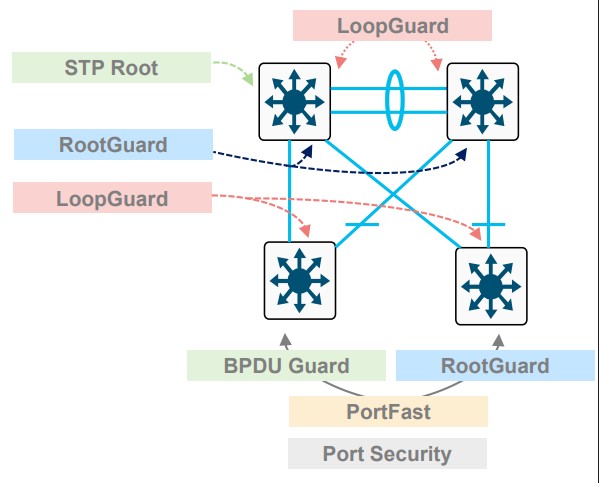
Image courtesy of BRKENS-2031.
References
Cisco Live - Enterprise Campus Design - Marcin Hamróz, and Jarosław Gawron - BRKENS-2031
Loop Guard
A unidirectional failure on a root or alternate port will cause spanning tree to loop.
Loopguard enforces a simple rule.
If a port was receiving BPBUs and suddenly it stops, don’t change the STP.
- This is one of the unidirectional preventatives
- This is only for switch-to-switch ports
… if a port doesn’t get a BPDU, it enters STP loop-inconsistent disabling the port.
Terms
Unidirectional Link
A failure where one side of a fiber pair is broken.
A unidirectional failure will always result in one side not getting information.
- SW1 sends BPDUs
- SW2 never gets BPDUs
Topology
- SW1 is a root bridge
- SW2 is experiencing a UL failure
- SW2 will transition Port 1 to a RP
                                                      No BPDU Received
┌────────────────────┐                            ┌────────────────────┐
│     ┌─────────────┐│                            │ ┌────────────┐     │
│     │ Port ┌────┐ ││ BPDU ────►XXXX             │ │┌────┐ Port │     │
│     │  1   │ TX ├─││────────────── Fiber Cut! ──│─│┤ RX │  1   │     │
│ SW1 │      └────┘ ││                            │ │└────┘      │ SW2 │
│     │  RP  ┌────┐ ││                            │ │┌────┐  DP  │     │
│     │      │ RX ├─││────────────────────────────│─│┤ TX │      │     │
│     │      └────┘ ││                ◄───── BPDU │ │└────┘      │     │
│     └─────────────┘│                            │ └────────────┘     │
└────────────────────┘                            └────────────────────┘
Config
Default
spanning-tree loopguard default
Per port
interface 1
  spanning-tree guard loop
References
Understand STP Loop Guard and UDLD Features - Cisco
UplinkFast
An older feature, doesn’t work with rapid-pvst, or MST.
- Bypasses listening and learning states.
- Blasts fake traffic out the UplinkFast Port to program the upstream CAM tables.
- Only recommended on the access layer.
Config
spanning-tree uplinkfast
Validation
Port costs are raised by 3000.
access# show spanning-tree

VLAN0001
  Spanning tree enabled protocol ieee
  Root ID    Priority    24577
             Address     5254.00bf.ea62
             Cost        3004
             Port        1 (GigabitEthernet0/0)
             Hello Time   2 sec  Max Age 20 sec  Forward Delay 15 sec

  Bridge ID  Priority    49153  (priority 49152 sys-id-ext 1)
             Address     5254.007a.bd39
             Hello Time   2 sec  Max Age 20 sec  Forward Delay 15 sec
             Aging Time  15  sec
  Uplinkfast enabled

Interface           Role Sts Cost      Prio.Nbr Type
------------------- ---- --- --------- -------- --------------------------------
Gi0/0               Root FWD 3004      128.1    P2p
Gi0/1               Altn BLK 3004      128.2    P2p

!
! After shutting down the port in CML
!
*Jun  4 02:41:34.557: %SPANTREE_FAST-7-PORT_FWD_UPLINK: VLAN0001 GigabitEthernet0/1 moved to Forwarding (UplinkFast).
References
Port Security
The default settings for port security will not age out learned mac addresses. To get aging back to the mac address table default of 5 minutes, set this feature to 5.
Config
interface GigabitEthernet0/0
 switchport access vlan 10
 switchport mode access
 switchport port-security maximum 2
 switchport port-security aging time 5
 switchport port-security
 negotiation auto
 spanning-tree portfast edge
Validation
This is the primary table for this feature. This table is used to populate the mac address table.
switch# show port-security address
               Secure Mac Address Table
-----------------------------------------------------------------------------
Vlan    Mac Address       Type                          Ports   Remaining Age
                                                                   (mins)
----    -----------       ----                          -----   -------------
  10    5254.000d.6573    SecureDynamic                 Gi0/0       10
-----------------------------------------------------------------------------
Scraping the mac-address table for things programmed in by the port security feature.
switch# show mac address-table secure
          Mac Address Table
-------------------------------------------

Vlan    Mac Address       Type        Ports
----    -----------       --------    -----
  10    5254.000d.6573    STATIC      Gi0/0
Asking port security how many ports are currently controlled by the feature.
switch #show port-security
Secure Port  MaxSecureAddr  CurrentAddr  SecurityViolation  Security Action
                (Count)       (Count)          (Count)
---------------------------------------------------------------------------
      Gi0/0              2            1                  0         Shutdown
---------------------------------------------------------------------------
Total Addresses in System (excluding one mac per port)     : 0
Max Addresses limit in System (excluding one mac per port) : 4096
References
Cisco - Port Security - IOS-XE 17.14 on the C9300
UDLD
This is the more common way to prevent ULD Failures, enabling ULD.
- ULD: Unidirectional Link Detection.
This feature has two modes:
-
Normal: Detect a fiber port that’s miss-cabled. Maybe port 1 and port 2 (four fibers total) got mixed up.
-
Aggressive: Detect one way traffic on both fiber, and twisted pair.
From Cisco:
- On fiber-optic or twisted-pair links, one of the ports cannot send or receive traffic.
- On fiber-optic or twisted-pair links, one of the ports is down while the other is up.
- One of the fiber strands in the cable is disconnected.
Requirements
- Both devices need this feature turned on.
- Both sides need the same mode (normal or aggressive)
Global
udld enable
Per interface
interface 1
  udld enable
Verification
sw1# show udld neighbors
Port     Device Name   Device ID     Port ID    Neighbor State
----     -----------   ---------     -------    --------------
Gi0/0    91YBLF6S1KI     1            Gi0/0      Bidirectional
Capture
Reference
Layer 2 Configuration Guide, Cisco IOS XE 17.16.x (Catalyst 9500 Switches)
VTP
Caution
VTP Melts Networks.
See VTP Bomb.
VTP — Vlan Trunk Protocol
- Cisco proprietary
- Runs on trunk ports
- Comes in three versions
- Defaults to v1
Design guidance
transparent or off.
See BRKENS-2031.
Modes
Server
- Create, Modify, Delete
- Default
- Other Servers can modify based on Revision
Client
- Gets VLANs from a server
Transparent
- Don’t program the control plane of this device with any recieved VTP packets
- Forward any received VTP packets recieved to other trunk links
- A version 2 thing
Off
- Don’t program the control plane
- Do not forward VTP
Version 3
- Saves VLANS to
vlan.dat - Primary and secondary servers
- Default is secondary
- Private VLANs
- Extended VLANs
- 1006 to 4094
- Propigating MST info
References
Configure VTP - VLAN Configuration Guide - IOS XE 17.18.x - Cisco
Cisco Live - Enterprise Campus Design - Marcin Hamróz, and Jarosław Gawron - BRKENS-2031
VTP Bomb
Caused when one VTP switch overwrites the VLANS of other VTP switches.
See VTP Design Guidance.
Terms
VBS — VTP Bomb Switch
- Usually sits around for a bit until it’s plugged back in
VTP isn’t really client-server
It operates more like peer-to-peer.
VTPv1 and VTPv2 allow multiple switches to be servers.
Any server switch can make VLAN changes.
VTP ties the desired VLAN state to configuration revision number
Setup one - repurposed decom
- VTP revision number: 50
- VTP mode: server
- Switch is removed
- VLANs deleted
- VTP revision number: 58
- VBS Created
- Stored
- Pulled out of storage
- Plugged into trunk port
- Has higher revision number
- Deletes VLANs
Setup two - site move
- VTP revision number: 21
- VTP mode: server
- Multisite network
- Templated config
- Same VTP domain everywhere
- Biggest site
- VBS Created
- Stored
- Site-B has revision: 15
- Site-B needs a new switch
- VBS is used
- Pulled out of storage
- Goes to Site-B
- Plugged into trunk port
- Has higher revision number
- Deletes VLANs
Setup three - lab work
- VTP revision number: 38
- VTP mode: server
- Junior engineer
- Doesn’t fear VTP
- Disconnects a switch from production
- Takes to desk
- Practices with making vlans
- VTP revision number: 45
- VBS Created
- A switch is needed for an expansion
- VBS is used
- Taken off desk
- Plugged into trunk port
- Has higher revision number
- Deletes VLANs
Stories
JumpyMud7539
I’ve just recovered from over writing a hospitals vlan database when collecting a new looking switch from the store room that was unboxed and installing it in the production network without really checking the running config.
VTP obviously had it’s own agenda. I am a network engineer who boasts no qualifications just experience on the job and the ability to blog my way through.
I must say when things go catastrophically wrong is when I learn best. I’m surrounded by good engineers who say that what they teach you in certifications gives you good theory but it doesn’t always relate to production environments.
As soon as it happened, I knew the problem and how to fix it regardless, I became too complacent. I wont lose my job, but i felt really bad. I feel I’ve learned a good lesson, I’ve learnt more about vtp, what we need to do going forward.
The organisation has also agreed to put me on a ccna course to enable me to progress.
FLATLANDRIDER
Setting up a new switch at a remote site. Cisco switch with VTP deployed.
I set up the basics and was getting VTP set up. The device was in client mode but I needed to change the VTP version.
Well you can only change the version in server mode. So I changed it to server mode so I could change the version.
As soon as I did that I lost connection to the remote site. The switch had pushed its empty vlan database to all other switches in the site, deleting all vlans. Even the true VTP server was overwritten.
I took the entire remote site down, which was in a different country. I ended up having to remote into someone’s computer using their hotspot so I could gain access to the core switch (VTP server) and recreate the vlan database.
Win_Sys
I think we have all done this at one point or another.
I took down an entire school once when I didn’t check VTP. Wiped the DC switch of most of its VLANs.
[deleted]
VTP mess-up (yes, I know)
I am a student employee, and I have been put in charge of re-speccing our VTP so we avoid the typical vulnerability of VTP where you plugin a switch from a different location and wipe out the whole HO. (Very grateful for the responsibility, but it makes my nuts sweat, tbh).
So in my department we are connected to switch A.
- In server-mode
- Pruning enabled
- Password enabled
- Version 2
So I think “aight, let’s go”, and change it to the new domain. 5 seconds later 30 employees are DC. I panick (not too hard anyway).
My superior doesn’t know what happened, tries to pick up the pieces, but my console window breaks down.
We connect to the switch via console.
Turn it back to the old domain
VOILA, it works!
I don’t dare touch VTP again.
Dear /networking, what happened?!
gypsy_endurance
Back in 2001’ish, was working Tier 2 networking shop at a Fin Srv company.
I was adding two 1RU switches to a very large Cisco campus network for a particular business unit (The Bond Pit).
Anyhoo, prestaged everything at my desk and waited for the change window. Plugged the switches in and was looking through some operational commands when a guy walks in and says “are you doing something with the network?”
I walk out of the room I’m in following him and about 30+ bond traders are standing up at their desks with their hands in the air complaining about the network being down.
The engineer that did the configs I was implementing, looked at the configs on the 6500s that we were uplinked to and all the vlans were gone.
Long story, shortened…Cisco’s client/server VTP feature didn’t actually act like a client/server.
The configuration revision in the VTP database was higher, or lower (don’t remember anymore) on the 1RU Cisco “clients” and overwrote the vlan database on the “server” 6500s.
The Cisco TAC case answer was “that’s how it’s supposed to work.” Talking about fearing for your job for the next 12 hrs. LOL!
Joe Morris
Plugged a previous used switch into a switched network. All Cisco. Running VTP
The newly connected switch won the vtp war and wiped the vlan db from all other switches.
Metro Ethernet
General caveats
- Shut down interfaces before configuring (best practice on ME3400)
- No DTP — dynamic trunk negotiation does not exist
- No VTP — VLAN Trunking Protocol does not exist
- Default STP mode is PVST
- Typically deployed as the last hop (service provider edge / CPE)
- Port model is based on port-types and UNI VLANs rather than standard IOS switchport modes
Port types (MEF terminology)
UNI — user network interface
- Connects to customer end devices (phones, computers, routers at the customer site)
- All ports except uplinks default to UNI
- Can only forward traffic toward NNI ports
- No STP
- No CDP
- No Link Aggregation
ENI — enhanced network interface
- Connects to routers or switches (slightly trusted devices)
- Supports STP
- Supports CDP
- Supports Link Aggregation
NNI — network node interface
- Network-to-Network — connects to other provider nodes/uplinks
- No Layer 2 protocol filtering — passes BPDUs, CDP, etc. transparently
Port type comparison
| Feature | UNI | ENI | NNI |
|---|---|---|---|
| STP | ✗ | ✓ | ✓ |
| CDP | ✗ | ✓ | ✓ |
| Link Aggregation | ✗ | ✓ | ✓ |
| L2 Protocol Filtering | ✓ | ✓ | ✗ |
| Customer-facing | ✓ | ✓ | ✗ |
Private VLANs
Default port type on a Catalyst ME3400 is UNI (User Network Interface)
UNI ports can only send traffic to NNI ports in the same vlan. The default UNI mode is isolated.
show vlan uni-vlan type
show port-type
You can set the uni-vlan type with this command:
vlan 100
  uni-vlan community
This example uses a ME3400.
Config example
vlan 100
private-vlan primary
private-vlan association 1000,2000,3000
!
vlan 1000
private-vlan isolated
!
vlan 2000
private-vlan community
!
vlan 3000
private-vlan community
!
!
interface FastEthernet0/2
!
! Tell it its a private-vlan host
! Tell it which private VLANs its in
!
 switchport private-vlan host-association 100 1000
 switchport mode private-vlan host
 duplex full
end
!
interface GigabitEthernet0/1
 port-type nni
 switchport private-vlan mapping 100 1000,2000,3000
 switchport mode private-vlan promiscuous
 speed nonegotiate
end

vlan 100
 private-vlan association add ... this doesn't work at all!!
Verification
switch #show vlan private-vlan

Primary Secondary Type              Ports
------- --------- ----------------- ------------------------------------------
100     1000      isolated          Fa0/1, Fa0/2, Gi0/1
100     2000      community         Fa0/3, Fa0/4, Gi0/1
100     3000      community         Gi0/1

SW1#show vlan private-vlan type

Vlan Type
---- -----------------
100  primary
1000 isolated
2000 community
3000 community
MPLS
MPLS requires CEF
Frame format
  RFC 3032 - MPLS Label Stack Encoding

  0                   1                   2                   3
   0 1 2 3 4 5 6 7 8 9 0 1 2 3 4 5 6 7 8 9 0 1 2 3 4 5 6 7 8 9 0 1
  +-+-+-+-+-+-+-+-+-+-+-+-+-+-+-+-+-+-+-+-+-+-+-+-+-+-+-+-+-+-+-+-+ Label
  |                Label                  | Exp |S|       TTL     | Stack
  +-+-+-+-+-+-+-+-+-+-+-+-+-+-+-+-+-+-+-+-+-+-+-+-+-+-+-+-+-+-+-+-+ Entry

                      Label:  Label Value, 20 bits
                      Exp:    Experimental Use, 3 bits
                      S:      Bottom of Stack, 1 bit
                      TTL:    Time to Live, 8 bits
MPLS control plane
| Table | Short Form | Notes | Command |
|---|---|---|---|
| Routing Information Base | RIB | The Best Path | show ip route |
| Label Information Base | LIB | All labels we’ve heard | show mpls ldp binding |
| Label Forwarding Information Base | LFIB | The best label | show mpls forwarding |
| LDP Peers | - | Who provides labels | show mpls ldp neighbors |
Local Label - This is what the LSP tells others it wants to recieve.
Outgoing label - What the LSP does next.
Null labels
[3] Implicit Pop the label. Implicit because the label is missing.
[0] Explicit Keep the label, but the destination must pop it. Used for MPLS QoS.
Steps to build the LFIB
1. Find the Next-Hop for the destination prefix
show ip route 3.3.3.4
 * 10.1.2.1, from 10.1.2.1 via Eth0/0
2. Confirm the LDP neighbor behind that Next-Hop
show mpls ldp neighbor 10.1.2.1
 * peer LDP ident 3.3.3.3; Local LDP ident 2.2.2.2
3. Check what label that peer advertised for the prefix
show mpls ldp binding 3.3.3.4 255.255.255.255
 * remote binding: lsr: 3.3.3.3, label: imp-null
4. Verify the resulting LFIB entry
show mpls forwarding 3.3.3.4
- Local 20, Outgoing Pop, Prefix 3.3.3.3/32, Outgoing Int E0/0, Nexthop 10.1.2.1
Testing pseudowires
You can test MPLS pseduowire labels by doing labeled pings.
ping mpls pseudowire 3.3.3.3 11000
L3VPN
Customer Exchanges routes with the provider via a routing protocol
VPN just means isolation. No encryption or confidentiality
PE-CE links are their own island
VRF = VPN Routing Forwarding Instance
You can use loopbacks to route between VRFs
L3VPNs rely on Extended Comunnities.
- Basically just arbitrary TLVs attached to BGP prefixes
VPNV4 = PE to PE Label Information ipv4 unicast vrf = BGP within vrfs for PE to CE connectivity
Example
router bgp 100
 neighbor 3.3.3.3 remote-as 100  ! note the neighbor is the same AS, this is the PE
!
address-family vpnv4
 neighbor 3.3.3.3 activate ! this is a global neighbor, part of our network
 neighbor 3.3.3.3 send-community extended
!
address-family ipv4 unicast vrf red
 neighbor 4.4.4.4 remote-as 400 ! Customer neighbor, in their own VRF instance
 neighbor 4.4.4.4 activate ! this is if you speak BGP to them. It could be any VRF aware IGP. You need to redistribute from the IGP into BGP
Route distinguishers
- ALL CE routes from ALL VRFs are placed into the same VPNv4 table. What makes them unique to vrfs are the RDs.
- Transparent to the customer, and only lives on the PE router
100:100:192.168.10/24
Route targets
- This is the BGP extended community
route-target exportadds the community to the outbound updateroute-target importdefines what routes to bring into the VRF
One RD per customer site.
show ip bgp vpnv4 all sum VPNv4
show ip bgp sum IPv4
LDP label gets from PE to PE VPN label identifies VRF to remote PE
MPLS DiffServ
-
Network is a single DiffServ Domain
-
ip2mpls Copy DSCP to EXP
-
mpls2mpls Copy EXP Upward and Downward
-
mpls2ip Copy EXP into the DSCP
-
Uniform changes the markings.
Short-Pipe
- Customer network is a different DiffServ Domain
- ip2mpls # Maybe copy
- Copy top EXP into lower labels.
- Use the exposed DSCP when there is no label.
- When mpls2ip is done, act on the ip information not the prior EXP bits.
Pipe mode (multiple DiffServ domains, default, no change to CE marking)
- ip2mpls # Maybe copy DSCP to EXP.
- SP MPLS exp may be remarked in transit
- IPv4 is not remarked at egress
- Customer marking is unchanged.
- mpls2ip operation is based on what the prior MPLS EXP tag was.
- Must shut off PHP
References
RFC 3270: Multi-Protocol Label Switching (MPLS) Support of Differentiated Services | RFC Editor
IRB on the ASR9K
10.0.0.2/24

 ┌───────┐
 │Host A │
 └───┬───┘
     │  VLAN                                                                  ASR 9k
     │   10
     │          ┌─────────────────────────────────────────────────────────────────────────────────────────────────────────────────────────┐
     │          │            Sub-interfaces                                Bridiging Domain                       Routing Domain          │
     │          │                                          ┌────────────────────────────────────────────────────────────────────────────┐ │
     │          │ ┌──────────────────────────────────────┐ │                                                 |                          │ │
     │          │ │interface g0/0/0/2.10 l2transport     │ │                                                 |                          │ │
     │          │ │  no ip address                       │ │ ┌─────────────────────────────────────────────┐ |                          │ │
     │ g0/0/0/1 │ │  encapsulation dot1q 10 exact        │ │ │ L2vpn                                       │ |                          │ │
     └──────────┼─┤  rewrite ingress tag pop 1 symmetric ├─┼─┤   bridge group BG_test                      │ |                          │ │
                │ └──────────────────────────────────────┘ │ │     bridge-domain BD_1                      │ |         BVI              │ │
                │                                          │ │       interface Gigabit Ethernet 0/0/0/1.10 ├─────────────               │ │
       g0/0/0/2 │ ┌──────────────────────────────────────┐ │ │       interface Gigabit Ethernet 0/0/0/2.10 │ |                          │ │
     ┌──────────┼─┤interface-g0/0/0/2.10-l2transport     ├─┼─┤     routed interface BVI 10                 │ | interface BVI 10         │ │
     │          │ │  no ip address                       │ │ └─────────────────────────────────────────────┘ |   ipv4 address 10.0.0.1  │ │
     │          │ │  encapsulation dot1q 10 exact        │ │                                                 |                          │ │
     │          │ │  rewrite ingress tag pop 1 symmetric │ │                                                 |                          │ │
     │          │ └──────────────────────────────────────┘ │                                                 |                          │ │
     │          │                                          │                                                 |                          │ │
     │ VLAN     │                                          └────────────────────────────────────────────────────────────────────────────┘ │
     │  10      └─────────────────────────────────────────────────────────────────────────────────────────────────────────────────────────┘
 ┌───┴───┐
 │Host B │
 └───────┘
10.0.0.3/24
Simple BBA on the ASR 1k
BBA — Broadband Aggregation
Pulled from very old notes :)
BBA
!
! ASR1k
!
bba-group pppoe PPPOE_USERS
  virtual template 1
!
interface Virtual-Template1
 ip address 10.10.10.1 255.255.255.0
 peer default ip address dhcp
 ppp authentication pap
Client
2800 Side

Current configuration : 76 bytes
!
interface Dialer1
 ip address dhcp
 encapsulation ppp
 dialer pool 1
!
interface FastEthernet0/0
 no ip address
 duplex auto
 speed aut
 pppoe enable
 pppoe-client dial-pool-number 1
end
PBB
PBB 802.1ah PBB or MAC-in-MAC)
graph LR
    CE1([CE]) ---|UNI .1ad| PEB1[PEB]
    CE2([CE]) ---|UNI .1ad| PEB2[PEB]

    subgraph AL["Access Network · 802.1ad"]
        PEB1 --- PBa1[PB]
        PEB2 --- PBa1
        PBa1 --- PBa3[PB]
        PBa1 --- PBa2
        PBa2[PB] --- PBa3[PB]
    end

    PBa3 ---|UNI .1ah| BEB1
    PBa3 ---|UNI .1ah| BEB2

    subgraph CORE["Core Network · 802.1ah"]
        BEB1[BEB] --- BCB1[BCB]
        BEB2[BEB] --- BCB1
        BCB1 --- BCB2[BCB]
        BCB2 --- BCB3
        BCB1 --- BCB3[BCB]
        BCB3 --- BEB3[BEB]

    end

    BEB3 ---|UNI .1ah| PBb1

    subgraph AR["Access Network · 802.1ad"]
        PBb1[PB] --- PBb3[PB]
        PBb1 --- PBb2
        PBb2[PB] --- PBb3
        PBb3 --- PEB3[PEB]
    end

    PEB3 ---|UNI .1ad| CE3([CE])
Terms
-
PB: Provider Bridge.
-
PEB: Provider Edge Bridge.
-
B-Component: A bridging component contained in a BEB that bridges in provider space (Backbone MAC addresses, B-VLAN).
-
BCB: Backbone Core Bridge, An S-VLAN bridge used within the core of a PBBN.
-
BEB: Backbone Edge Bridge, A backbone edge bridge positioned at the edge of PBBN that encapsulates customer frames for transmission across a PBBN.
-
B-MAC: Backbone MAC Address. An individual MAC address associated with a Provider Instance Port (PIP) and used in creating the MAC header of I-tagged frames transmitted across a PBBN.
-
Backbone Service Instance: An instance of the MAC service in a PBBN provided between two or more Virtual Instance Ports (VIPs) in BEBs.
-
I-SID: Backbone Service Instance Identifier. A 24-bit field of the backbone service instance tag (I-TAG) that identifies the backbone service instance of a frame. The I-SID defines the service instance that the frame should be “mapped to”.
-
I-TAG Backbone Service Instance Tag. A tag with a Ethertype value allocated for IEEE 802.1q backbone service instance tag type.
-
B-TAG: Backbone VLAN Tag. A field defined in IEEE 802.1ah provider MAC encapsulation header that conveys the backbone VLAN ID information. The format of the B-TAG is same as that of an IEEE 802.1ad S-TAG field.
-
CBP: Customer Backbone Port. A BEB port that can receive and transmit I-tagged frames for multiple customers,
and can assign B-VIDs (backbone VLAN IDs) and translate I-SID on the basis of the received I-SID.
- I-Component: A bridging component contained in a BEB that bridges in the Customer space (Customer MAC addresses, S-VLAN).
- PIP: Provider Instance Port. The set of Virtual Instance Ports (VIPs) that are supported by a single instance.
- Service frame: A frame exchanged between a provider and a customer.
- VIP: Virtual Instance Port. A bridge port on an I-Component in BEB that provides access to a single backbone service instance.
References
SPAN, RSPAN, ERSPAN
Local
monitor session 1 source interface GigabitEthernet1/0/1 both
monitor session 1 destination interface GigabitEthernet1/0/2
RSPAN
- VLAN Encapsulated
- Does not support layer 2 protocols
- No CDP, BPDUs, LLDP, etc
- If the source is a trunk port, you can use the
filterkeyword to select specific vlans
Source switch
vlan 3000
 remote-span
monitor session 1 source interface GigabitEthernet1/0/1 both
monitor session 1 destination remote vlan 3000
Destination switch
vlan 3000
 remote-span
monitor session 1 source remote vlan 3000
monitor session 1 destination interface GigabitEthernet1/0/2
ERSPAN
GRE Encapsulated.
These will encapsulate BPDUs and other Layer 2 protocols.
These need ip routing turned on.
These do not support QoS.
Source switch
monitor session 1 type erspan-source
 !
 ! Could also put a vlan here
 !
 source interface Gi2
 destination
  erspan-id 100
  ip address 10.0.12.2
  origin ip address 10.0.12.1
 no shutdown
Destination switch
monitor session 1 type erspan-destination
 destination interface Gi2
 source
  erspan-id 100
  !
  ! An outside address on this box, not a loopback.
  ! this is the de-encapsulation interface.
  !
  ip address 10.0.12.2
 no shutdown
References
Cisco - Configuring SPAN and RSPAN
Cisco - ERSPAN Restrictions (IOS XR)
Multicast
Invented by Steve Deering, in his 1991 PhD thesis work Multicast Routing in a Datagram Internetwork.
Multicast is always to a group, a destination, or a set of destinations.
Terms
Multicast
- A one-to-many service using UDP packets destined to group IP address
- Hosts subscribe to the group, routers and switches replicate for the group
IGMP — Internet Group Management Protocol
- Receivers send IGMP to LHR to request multicast streams
- Switches see IGMP (for snooping), and the LHR uses this to build the MDT
PIM — Protocol Independent Multicast
- Multicast capable routers communicate to each over via PIM
IIF — Incoming Interface
- AKA, the RPL interface
- Part of the MDT
OIL — Outgoing Interface List
- Part of the MDT
MDT — Multicast Distribution Tree
- The full set of links participating in multicast, via PIM, IGMP, including IILs, and OILs
RP — Rendezvous Point
- A router designated as the root of a shared tree
(*, G)
- AKA, a shared tree
- Pronounced as “Star comma Gee”
- Require a RP
- Called Star comma Gee, because typing “show ip mroute” … this is what shows up
(S, G)
- AKA, a source tree
- These do not require a RP
- Pronounced as “Ess comma Gee”
Source Tree
- AKA, SPT
- Shortest path tree
- SPT is best tree
RPT — Rendezvous Point Tree
- *,G that points towards the RP
ASM — Any Source Multicast
- The host only knows the group it wants to receive (239.10.10.10)
SSM — Source Specific Multicast
- The host already knows the source, and group address (10.0.0.1, 232.10.10.10)
Upstream
- Towards the source
Downstream
- Towards group members
FHR — First hop router
- This router receives a multicast stream
LHR — Last Hop Router
- Receives IGMP messages from receivers, which are translated into PIM join messages
MRIB — Multicast Routing Information Base
- Shows RPTs, SPTs, RPFIs, OILs, and IILs
MFIB — Multicast Forwarding Information Base
- AKA MFIB
- Used the program the ASICS
RIB — Routing Information Base
DF — Designated Forwarder
- Used in PIDIR-PIM
RPF - reverse path forwarding
PIM is protocol independent, in the sense, that if a stream turns on, it must have a source, so it takes the form (0.0.0.1, 239.1.1.1), a (S,G).
If we do show ip route 10.0.0.1, we’ll see the interface the router intends to send any traffic towards that source address. This is the upstream interface.
As multicast traffic flows from 10.0.0.1, it should flow into the upstream interface, and out of any downstream interfaces the OIL.
Tracing the traffic back to the source this way is called reverse path forwarding and the interface along this path is the RPF.
The PIM neighbor on the RPF is called the RPF neighbor.
Any multi-cast traffic from any given source, not received on the RPF is discarded. This prevents loops.
Shared trees
(*,G) entries in the mroute table require fewer resources, since multiple sources can use the same tree.
(*,G) entries in the mroute table represent a security risk, because any source can send to this shared tree.
PIM
PIM forms adjacencies in only one direction.
The multicast source is the root of the tree. Packets flow downstream from the source. Control plane traffic like PIM joins flow upstream to the RP, or to the receiver.
PIM Modes
| PIM Mode | Full Name | How it works |
|---|---|---|
| PIM-DM | Dense Mode | No RP. Floods everywhere, routers send prune messages to un-join. Assumes everyone wants the traffic. |
| PIM-SM | Sparse Mode | Complex. Requires a RP, RP Discovery, and phases. Uses register messages, and both tree types. |
| PIM Sparse-Dense | Sparse-Dense Mode | Runs sparse for groups with a known RP, dense for groups without. Legacy transitional mode. |
| Bidir-PIM | Bidirectional | Shared tree only, traffic flows both toward and away from RP. No SPT switchover. Good for many-to-many applications. |
| PIM-SSM | Source Specific | No RP. Receiver specifies both source and group (S,G). |
PIM message types
| Type | Message Type | Destination | Purpose |
|---|---|---|---|
| 0 | Hello | 224.0.0.13 (all PIM routers) | Establish adjacency, negotiate parameters. |
| 1 | Register | RP address (unicast) | First-hop router notifies RP of new source, encapsulates multicast data until SPT is built. |
| 2 | Register stop | First-hop router (unicast) | RP tells first-hop router to stop sending Register messages. |
| 3 | Join/prune | 224.0.0.13 (all PIM routers) | Join or prune a multicast tree, either (*,G) toward RP or (S,G) toward source. |
| 4 | Bootstrap | 224.0.0.13 (all PIM routers) | BSR floods RP-set information throughout the domain so all routers know candidate RPs. |
| 5 | Assert | 224.0.0.13 (all PIM routers) | Elect a single forwarder on a multi-access segment when duplicate traffic is detected. |
| 8 | Candidate RP advertisement | Bootstrap router (BSR) (unicast) | Candidate RPs advertise themselves to the BSR. |
| 9 | State refresh | 224.0.0.13 (all PIM routers) | PIM-DM only. Prevents prune state from timing out and triggering a re-flood. |
| 10 | DF election | 224.0.0.13 (all PIM routers) | Bidir-PIM only. Elects a Designated Forwarder per link to forward traffic toward the RP. |
Shared-Tree (*,G)
-
Shared trees are essential for multiple senders to the same group
-
A single tree is built for each group, regardless of source
- 3 sources, 1 tree
-
Selects a router as the root of the tree
-
If a receiver is on the same subnet as the sending host, it will need to revert to PIM Dense for that segment
-
This isn’t always better. Shared trees will typically take suboptimal paths through a network
-
Source trees are better distributed, hence they are more robust
-
RP Selection is a hassle
Source based multicast (S,G)
- PIM dense uses a separate tree for each multicast source and destination group
- Groups do not share trees
- 3 Sources 3 trees
Commands
show mrib route
show ip mroute
!
! PIM
!
show pim rpf hash
show pim range-list
show pim topology
!
! What interface should I receive this host traffic from?
!
show ip rpf 10.0.0.0
show ip mfib
!
! See if multicast even works
!
show ip pim stats
!
! PIM traffic
!
show ip pim interface detail
!
! DF election
!
show ip pim interface df
FLAGS
 A - Accepting. This interface is accepting data
 F - Forwarding. Where to send multicast traffic
Nexus 7K
show forwarding multicast route group <>
Lab stuff
BPF - Capture all PIM, but not PIM hello messages.
ip proto 103 and not ether[34] == 0x20
References
PIM Dense
Based on RFC 3973 Protocol Independent Multicast Dense Mode (PIM-DM)
-
Push Model
- Good for when every subnet probably wants this traffic
-
No PIM DR
- All FHR forward multicast traffic
- Multicast traffic is flooded out every interface that isn’t the RPF.
- All FHR forward multicast traffic
-
Eventually builds a SPT after prunes
-
IGMP joins turn into graft messages
-
Prunes last 3 minutes
- Flood and Prune
- Routers with no Receivers or duplicate S,G traffic prune.
224.0.0.13to find neighbors- Receivers prune back
- Router attached to LAN listens for multicast control plane.
- Receives source traffic
- Insert (*,G) and (S,G) into mrib
- Incoming traffic is attached to IIL
- OIL is all other interfaces
- Flood to OIL
- PIM dense always uses SPT.
- Receives source traffic
-
Prune occurs
- Traffic flows stop, but (S,G) remains in table
- Multicast fails RPF
- No downstream neighbor or reciever
- Downstream sent prune
- LAN Prune override exception
-
After pruning
- Flood again, prune back, flood again, prune back
PIM Sparse
Based on RFC4601 - Protocol Independent Multicast Sparse Mode (PIM-SM)
- Explicit joins everywhere. No flooding.
- LHR, sends a PIM-Join towards the RP, building a (*,G).
- Phased
*
- Receivers sending their (*,G) messages towards the RP.
- FHR encapsulates the multicast traffic directly towards the RP.
- PIM-Register
- RP de-encapsulates the traffic, sending it down the RPT.
-
- The RP sends a (S,G) towards the source.
- When multicast packets start showing up, without encapsulation, the RP sends a Register-Stop.
-
- LHR requests a (S,G) entry towards it’s upstream, until it’s joined to the (S,G) tree.
- When the LHR starts getting two copies of the traffic, it sends a (S,G,rpt) prune message, towards the RP. (A prune specific to the RPT)
- If two LHRs exist, and duplicate traffic is detected a PIM elections happens.
- These Asserts are every 3 minutes.
- RPTbit, 0 is preferred and means “has (S,G) tree”
- Metric Preference (Administrative Distance)
- Metric
- IP address of subnet interface.
- Metric
- Metric Preference (Administrative Distance)
- Specify the tunnel, for the pim-register messages on Cisco via
ip pim register-source loopback 0 - The tunnel interface encapsulates the entire multicast packet, which adds 28 bytes of overhead. Packets close to the MTU will be silently dropped on IOS-XE.
a DR is elected by highest priority, or highest IP in the subnet.
- DR sends the PIM join upstream.
The RP always gets the stream, even if it has no receivers to forward it to.
Captures
PIM-SM-register-register-stop-prune.pcap
BIDIR-PIM
- Superset of PIM-SM
- No (S,G) entries
- Traffic can flow up and down the same tree.
- Still needs RPs
- RP must be dedicated to BIDIR-PIM.
- Each bidirectional link has a DF election.
- Ingress packets on any PIM interface can be forwarded downstream onto DF links.
- No DF links, no forwarding.
- Ingress packets to a DF can be forwarded upstream via the RPF towards the RPA.
- Ingress packets on any PIM interface can be forwarded downstream onto DF links.
References
RFC 5015: Bidirectional Protocol Independent Multicast (BIDIR-PIM) | RFC Editor
Auto-RP
Cisco devices can announce their willingness to be an RP, via cisco-rp-announce
A different service, a mapping agent, will read these messages, pick a winner, then advertise that out via cisco-rp-discovery
- 5.5.5.5, Candidate RP.
- 4.4.4.4, mapping agent.
R4# show ip pim autorp

AutoRP Information:

  AutoRP is enabled.
  RP Discovery packet MTU is 1500.
  224.0.1.40 is joined on Loopback0.
  AutoRP groups over sparse mode interface is enabled

PIM AutoRP Statistics: Sent/Received
  RP Announce: 0/16, RP Discovery: 64/42
These packets are slow.
R4# debug ip pim auto-rp

PIM Auto-RP debugging is on
!
! Sent to cisco-rp-discovery
!
*Apr 25 19:57:08.940: Auto-RP(0): Build RP-Discovery packet
*Apr 25 19:57:08.941: Auto-RP(0):  Build mapping (224.0.0.0/4, RP:5.5.5.5), PIMv2 v1,
*Apr 25 19:57:08.942: Auto-RP(0): Send RP-discovery packet of length 48 on GigabitEthernet0/3 (1 RP entries)
*Apr 25 19:57:08.943: Auto-RP(0): Send RP-discovery packet of length 48 on GigabitEthernet0/4 (1 RP entries)
*Apr 25 19:57:08.945: Auto-RP(0): Send RP-discovery packet of length 48 on GigabitEthernet0/0 (1 RP entries)
*Apr 25 19:57:08.948: Auto-RP(0): Send RP-discovery packet of length 48 on Loopback0(*) (1 RP entries)
*Apr 25 19:57:12.008: Auto-RP(0): Received RP-discovery packet of length 48, from 10.0.45.5, ignored
!
! Received by cisco-rp-announce
!
*Apr 25 19:58:30.159: Auto-RP(0): Received RP-announce packet of length 48, from 5.5.5.5, RP_cnt 1, ht 181
*Apr 25 19:58:30.159: (0): pim_add_prm:: 224.0.0.0/240.0.0.0, rp=5.5.5.5, repl = 0, ver =3, is_neg =0, bidir = 0, crp = 0
*Apr 25 19:58:30.160: Auto-RP(0): Update
*Apr 25 19:58:30.160:  prm_rp->bidir_mode = 0 vs bidir = 0 (224.0.0.0/4, RP:5.5.5.5), PIMv2 v1
R4# undebug all
All possible debugging has been turned off
References
Cisco - Configuring a Rendezvous Point
MSDP
- Link multicast domains via RPs
- Provide Redundant RPs via Anycast RP
A source turns on, and when the first RP finds out about it, it notifies other RPs.
Details
- RPs register to each other, in different multicast domains
- RP sends a SA (source active) message
- Still needs PIM running for the
S,G - TCP port 639
- Has keepalives
Startup
-
Multicast source starts up.
-
FHR router sends a register message to the closest RP.
-
RP registers this as a SA (Source Active).
-
Sends Source Active Messages to other RPs
(*,G) means there is an interested receiver.
Config
!
! RP1
!
int lo0
description "Only used for Anycast RP"
ip address 10.0.0.1 255.255.255.255
!
int lo1
ip add 10.1.1.1 255.255.255.255
!
ip msdp peer 10.1.1.2 connect-source loopback 1
ip msdp originator-id loopback 1
ip pim rp-address 10.0.0.1
!
! RP2
!
int lo 0
  description "Only used for Anycast RP"
  ip address 10.0.0.1 255.255.255.255
!
int lo1
  ip address 10.1.1.2 255.255.255.255
!
ip msdp peer 10.1.1.1 connect-source lo1
ip msdp originator-id loopback 1
ip pim rp-address 10.0.0.1
Commands
show ip msdp peer
show ip msdp sa-cache
References
RFC 4611 - Multicast Source Discovery Protocol (MSDP) Deployment Scenarios
IPv6 Multicast Addresses
Terms
NVO — Network Virtualization Overlay
- Stuff like VXLAN
BUM – Broadcast, Unknown Unicast, Multicast
- Traffic that is one-to-many
Interface local scope
- Never goes onto the wire
- Popular for neighbor discovery
Link local scope
- Never routed
| Addresses | Description | Reference |
|---|---|---|
| FF02::1 | All Nodes | 4291 |
| FF02::2 | All Routers | 4291 |
| FF02::3 | Unassigned | |
| FF02::4 | DVMRP Routers | 1075 |
| FF02::5 | OSPF | 2328 |
| FF02::6 | OSPF DR | 2328 |
| FF02::9 | RIP | 2080 |
| FF02::A | EIGRP | 7868 |
| FF02::B | Mobile-Agents | |
| FF02::C | SSDP | |
| FF02::D | PIM | |
| FF02::E | RSVP-ENCAPSULATION | |
| FF02::F | UPnP | |
| FF02::12 | VRRP | 9568 |
| FF02::14 | NVO BUM Traffic | 9624 |
| FF02::16 | All MLDv2 routers | 9777 |
| FF02::1A | all-RPL-nodes | 6550 |
| FF02::6A | MRD - All-Snoopers | 4286 |
| FF02::6B | PTP-pdelay | |
| FF02::6C | Saratoga | |
| FF02::FB | mDNSv6 | 6762 |
References
IPv6 Multicast Address Space - IANA
Multicast L2 Addressing
An L2 multicast address is 6 bytes, or 48 bits.
The address is built by combining these three things.
Multicast Prefix + 0 + low-order-23-bits-from-v4
Multicast prefix
The Multicast Prefix is 01:00:5E 3 bytes or 24 bits.
25th bit
A binary zero 0
Last 23 bits
Using 232.10.10.10
Copy the low order 23 bits directly from the v4 address.
232.10.10.10/8

1110 1000 . 0000 1010 . 0000 1010 . 0000 1010
             \______________________________/
000 1010 0000 1010 0000 1010
Building the address
Using 232.10.10.10
          1 :         0 :        5E :        0A :       0A  :        0A
  0000 0001 . 0000 0000 . 0101 1110 . 0000 1010 . 0000 1010 . 0000 1010
  \__________________________________/|\______________________________/
         Multicast Prefix             |   The 23 bits from the v4 IP
           Always 01:00:5E            |
                                      └─ The required zero bit for multicast
becomes 01:00:5E:0A:0A:0A
Multicast overlap
To express a v4 multicast address uniquely in L2 we need 28 bits, since the first 4 bits of every v4 multicast address are 1110
L2 in multicast only gets 23 bits, which means 5 bits of overlap.
2^5 is 32, so there are 32 v4 addresses that share the same L2 address.
All 32 IPv4 addresses mapping to 01:00:5E:0A:0A:0A
══════════════════════════════════════════════════════════════════════════════
Address           Octet 1    Octet 2    Octet 3    Octet 4
──────────────────────────────────────────────────────────────────────────────
224. 10.10.10     1110 0000  0000 1010  0000 1010  0000 1010
224.138.10.10     1110 0000  1000 1010  0000 1010  0000 1010
225. 10.10.10     1110 0001  0000 1010  0000 1010  0000 1010
225.138.10.10     1110 0001  1000 1010  0000 1010  0000 1010
226 .10.10.10     1110 0010  0000 1010  0000 1010  0000 1010
226.138.10.10     1110 0010  1000 1010  0000 1010  0000 1010
227 .10.10.10     1110 0011  0000 1010  0000 1010  0000 1010
227.138.10.10     1110 0011  1000 1010  0000 1010  0000 1010
228 .10.10.10     1110 0100  0000 1010  0000 1010  0000 1010
228.138.10.10     1110 0100  1000 1010  0000 1010  0000 1010
229 .10.10.10     1110 0101  0000 1010  0000 1010  0000 1010
229.138.10.10     1110 0101  1000 1010  0000 1010  0000 1010
230 .10.10.10     1110 0110  0000 1010  0000 1010  0000 1010
230.138.10.10     1110 0110  1000 1010  0000 1010  0000 1010
231 .10.10.10     1110 0111  0000 1010  0000 1010  0000 1010
231.138.10.10     1110 0111  1000 1010  0000 1010  0000 1010
232 .10.10.10     1110 1000  0000 1010  0000 1010  0000 1010  < --- This is our SSM address
232.138.10.10     1110 1000  1000 1010  0000 1010  0000 1010
233 .10.10.10     1110 1001  0000 1010  0000 1010  0000 1010  < --- An address in the GLOP block
233.138.10.10     1110 1001  1000 1010  0000 1010  0000 1010
234 .10.10.10     1110 1010  0000 1010  0000 1010  0000 1010
234.138.10.10     1110 1010  1000 1010  0000 1010  0000 1010
235 .10.10.10     1110 1011  0000 1010  0000 1010  0000 1010
235.138.10.10     1110 1011  1000 1010  0000 1010  0000 1010
236 .10.10.10     1110 1100  0000 1010  0000 1010  0000 1010
236.138.10.10     1110 1100  1000 1010  0000 1010  0000 1010
237 .10.10.10     1110 1101  0000 1010  0000 1010  0000 1010
237.138.10.10     1110 1101  1000 1010  0000 1010  0000 1010
238 .10.10.10     1110 1110  0000 1010  0000 1010  0000 1010
238.138.10.10     1110 1110  1000 1010  0000 1010  0000 1010
239 .10.10.10     1110 1111  0000 1010  0000 1010  0000 1010
239.138.10.10     1110 1111  1000 1010  0000 1010  0000 1010  < --- an Organizational scope address
══════════════════════════════════════════════════════════════════════════════
                       ^^^^  ^
                       ||||  |
                       └└└└──└─ I incremented these five bits to show the pattern.
References
RFC 1112: Host extensions for IP multicasting | RFC Editor
Multicast L3 Addressing
Bits
-
IPv4 L3 multicast address always start with
1110or224.0.0.0/4 -
IPv6 L3 multicast address always start with
1111 1111orff00::/8
L3 Ranges
IPv4
IPv4 combines scope and purpose in its address ranges.
| Block | Name / Type | Notes |
|---|---|---|
224.0.0.0/4 | IPv4 Multicast | Entire IPv4 multicast space (Class D) |
224.0.0.0/24 | Local Control | Not routed (TTL=1). Used by OSPF, EIGRP, mDNS, etc. |
224.0.1.0/24 | Internetwork Control Block | Routable (e.g. NTP, some vendor protocols) |
232.0.0.0/8 | Source-Specific Multicast (SSM) | (S,G) only. No RP. Defined in RFC 4607 |
233.0.0.0/8 | GLOP Addressing | Derived from 16-bit ASN deprecated |
239.0.0.0/8 | Administratively Scoped | Private multicast (like RFC1918). |
IPv6
IPv6 separates scope cleanly by last nibble in the first hextet.
| Block | Address Scope | Description |
|---|---|---|
| ff00::/8 | Supernet | All IPv6 multicast addresses |
| ff01::/16 | Interface-Local | Stays within a single interface (rarely used in practice) |
| ff02::/16 | Link-Local | Local link only (no routing). Most control protocols live here |
| ff03::/16 | Realm-Local | Defined by an admin “realm” (rare / niche usage) |
| ff04::/16 | Admin-Local | Administrative domain (like a small org boundary) |
| ff05::/16 | Site-Local | Site scope (similar intent to IPv4 org-local, but loosely defined) |
| ff08::/16 | Organization-Local | Organization-wide scope (closest to 239.0.0.0/8 in spirit) |
| ff0e::/16 | Global | Globally routable multicast |
L3 addresses Combines IPv4 and IPv6
L3
IL — Interface-Local
- Node only
- Not transmitted
- Never on the wire
LL — Link-Local
- TTL of 1
- Transmitted
- On the wire
SL — Site-Local
- Routeable
- Not Global Internet
L2 and L3
- IPv4 is always
01:00:5e - IPv6 is always
33:33:00
| Protocol / Group | IPv4 | IPv4 L2 MAC | IPv6 LL | IPv6 L2 MAC |
|---|---|---|---|---|
| All Nodes | 224.0.0.1 | 01:00:5e:00:00:01 | ff02::1 | 33:33:00:00:00:01 |
| All Routers | 224.0.0.2 | 01:00:5e:00:00:02 | ff02::2 | 33:33:00:00:00:02 |
| OSPF All Routers | 224.0.0.5 | 01:00:5e:00:00:05 | ff02::5 | 33:33:00:00:00:05 |
| OSPF DR/BDR | 224.0.0.6 | 01:00:5e:00:00:06 | ff02::6 | 33:33:00:00:00:06 |
| RIPv2 / RIPng | 224.0.0.9 | 01:00:5e:00:00:09 | ff02::9 | 33:33:00:00:00:09 |
| EIGRP | 224.0.0.10 | 01:00:5e:00:00:0a | ff02::a | 33:33:00:00:00:0a |
| MLD | - | - | ff02::16 | 33:33:00:00:00:16 |
| VRRP | 224.0.0.18 | 01:00:5e:00:00:12 | ff02::12 | 33:33:00:00:00:12 |
| PIM / BSR | 224.0.0.13 | 01:00:5e:00:00:0d | ff02::d | 33:33:00:00:00:0d |
| IGMPv3 | 224.0.0.22 | 01:00:5e:00:00:16 | - | - |
| Cisco Auto-RP Announce | 224.0.1.39 | 01:00:5e:00:01:27 | - | - |
| Cisco Auto-RP Discovery | 224.0.1.40 | 01:00:5e:00:01:28 | - | - |
| NTP | 224.0.1.1 | 01:00:5e:00:01:01 | ff02::101 | 33:33:00:00:01:01 |
| mDNS | 224.0.0.251 | 01:00:5e:00:00:fb | ff02::fb | 33:33:00:00:00:fb |
IGMPv3
IGMP — Internet Group Membership Protocol
Hosts show interest in IPv4 multicast groups with IGMPv3.
Multiple group records can fit into a single report.
 0                   1                   2                   3
 0 1 2 3 4 5 6 7 8 9 0 1 2 3 4 5 6 7 8 9 0 1 2 3 4 5 6 7 8 9 0 1
┌───────────────┬───────────────┬───────────────────────────────┐
│  Type = 0x22  │    Reserved   │           Checksum            │
├───────────────┴───────────────┼───────────────────────────────┤
│             Flags             │  Number of Group Records (M)  │
├───────────────────────────────┴───────────────────────────────┤
│                                                               │
│                                                               │
│                        Group Record [1]                       │
│                                                               │
│                                                               │
├──────────────────────────────────────────────────────────────-│
│                                                               │
│                                                               │
│                        Group Record [2]                       │
│                                                               │
│                                                               │
└───────────────────────────────────────────────────────────────┘
References
RFC 9776: Internet Group Management Protocol, Version 3 | RFC Editor
Static Routing
Static routes cannot respond to things like bandwidth, delay, load, or reliability.
These routes are a choice where there is no alternative path.
Config
Normal Route
ip route 0.0.0.0 0.0.0.0 192.168.0.1
Floating Static
Maybe the network already has a default route from an IGP like OSPFv2.
Since the OSPFv2 route is already present this won’t be installed.
We call that floating.
!
! 225 is a higher administrative distance than EIGRP, OSPF, ISIS, iBGP, and eBGP.
!
ip route 0.0.0.0 0.0.0.0 192.168.0.1 225
References
Static Routing - IP Routing Configuration Guide, IOS-XE 17.x - Cisco
OSPFv2
OSPFv2 is protocol 89.
Terms
LS — Link State
LSA — Link State Advertisement
LSDB — Link-State Database
RID — Router ID
- Unique 32-bit number to identify the router in a graph
- Doesn’t have to be an on-the-box IP, but is usually a loopback
- Should be easy to identify from a Router-ID subnet
Process ID
- Where the databases lives
- Not transmitted
- Allows multiple OSPFv2 processes
DR — Designated Router
- Network vertex for a broadcast or NBMA network
- Used to reduce the number of FULL adjacencies
Advertising Router
- Router that created the LSA
- Value in this field is the RID
The Update Rule
- Routers can only modify LSAs they originate
- Its RID is inside the “Advertising Router” field
LS Sequence
- The first sequence number in any LSA is
0x80000001 - Higher sequence numbers are newer LSAs
LS Checksum
- Used to ensure the LSA was transmitted without corruption
- Everything is checked except LS Age
LS Age
- LSAs time out in an hour
- Refreshed every 30 minutes
- LSA Age increments traveling through routers
IFF — If and only if
Packet types
| Type | Name | Short Name | Purpose |
|---|---|---|---|
| 1 | Hello | Hello | OSPFv2 puts the neighbor ID into it’s hello messages |
| 2 | Database Description | DBD/DDP | A LSA that contains LSA headers, “I have these LSAs” |
| 3 | LS Request | LSR | Requesting a specific LSA |
| 4 | LS Update | LSU | Send a specific LSA |
| 5 | LS Acknowledgment | LSAck | Acknowledging a specific LSA |
Hello packets
These things must match for an adjacency to form
- Hello time
- Dead time
- Subnet
- Subnet mask
- Interface MTU
- Area
- Area flags (NSSA, Stub)
- Is DR/BDR enabled
- Authentication
These must not match
- Router ID
Check with debug ip ospf event
Identical databases
Each router can perform its own SPT via Dijkstra’s algorithm.
LSAs are flooded throughout an area, all routers in the same area should have the same LSAs and same database.
R1# show ip ospf database database-summary  | s Area 0
Area 0 database summary
  LSA Type      Count    Delete   Maxage
  Router        5        0        0
  Network       5        0        0
  Summary Net   8        0        0
  Summary ASBR  2        0        0
  Type-7 Ext    0        0        0
    Prefixes redistributed in Type-7  0
  Opaque Link   0        0        0
  Opaque Area   0        0        0
  Subtotal      20       0        0
R2# show ip ospf database database-summary | s Area 0
Area 0 database summary
  LSA Type      Count    Delete   Maxage
  Router        5        0        0
  Network       5        0        0
  Summary Net   8        0        0
  Summary ASBR  2        0        0
  Type-7 Ext    0        0        0
    Prefixes redistributed in Type-7  0
  Opaque Link   0        0        0
  Opaque Area   0        0        0
  Subtotal      20       0        0
Can also check with checksums
show ip ospf | i Checksum
Adjacency state machine
| State | Description |
|---|---|
| Down | OSPFv2 is running, no hello packets received yet. |
| Attempt | NBMA mode, the router has sent OSPFv2 packets. |
| Init | The router sees hello packets. |
| 2-Way | The router sees it’s own router-id in the hello packet. |
| ExStart | Routers vote on who exchanges LSDB first. |
| Loading | Router DB has been exchanged, router is requesting specific LSAs. |
| Full | LSDBs for this area are identical on both sides. |
Routing hierarchy
OSPFv2 has four levels of routing hierarchy.
| Preference | Route | Purpose |
|---|---|---|
| 1 | O | Intra-area (same area) |
| 2 | O IA | Inter-area (same OSPFv2 domain) |
| 3 | E1 | External type 1 (seed metric + IGP metric) |
| 4 | E2 | External type 2 (just seed metric) |
The bit E is what makes E1 and E2 routes. The bit being set is an E2 route, which is considered less preferred.
Default route
OSPFv2 has two ways of originating a default route.
default-information originate if a default route is present.
default-information originate always do it anyway.
Cost
Should be set manually on each node.
The defaults make 100Mbps and above all the same cost.
auto-cost reference-bandwidth 40,000
Area summary
These will show up as an O IA route in OSPFv2, and a route-to-null on the ABR.
- Requires a route present in the RIB
v4
router ospf 1
 router-id 2.2.2.2
 area 1 range 10.0.0.0 255.255.224.0
v6
router ospfv3 1
 !
 address-family ipv6 unicast
  area 1 range 2001:DB8::/56
Route-Filtering
You can use the same command to tell the router to … exclude these routes from the backbone, via the not-advertise keyword.
Using range
The area command is now a route-filter.
Range v4
router ospf 1
 router-id 2.2.2.2
 area 1 range 10.0.0.0 255.255.224.0 not-advertise
Range v6
router ospfv3 1
 !
 address-family ipv6 unicast
  area 1 range 2001:DB8::/56 not-advertise
 exit-address-family
Using Filter-Lists
These are a bit harder to use, in and out are inbound and outbound to the area.
For this topology
             Area 0                               Area 1

                                 |           10.0.10.0/24
                                 |         2001:db8:0:10/64
                                 |                            +----+
                              +----+       +------------------+ R3 |
+----+                        |    +-------+                  +----+
| R1 +------------------------+ R2 |
+----+                        |    +------+
             10.0.0.0/24      +----+      |                   +----+
           2001:db8:0:0/64       |        +-------------------+ R4 |
                                 |           10.0.20.0/24     +----+
                                 |         2001:db8:0:20/64
v4
ip prefix-list PREFIX_LIST_LOOPBACK_v4 seq 10 deny 1.1.1.1/32
ip prefix-list PREFIX_LIST_LOOPBACK_v4 seq 20 deny 2.2.2.2/32
ip prefix-list PREFIX_LIST_LOOPBACK_v4 seq 30 deny 3.3.3.3/32
!
router ospf 1
 area 0 filter-list prefix PREFIX_LIST_LOOPBACK_v4 in
 area 1 filter-list prefix PREFIX_LIST_LOOPBACK_v4 in
v6
!
ipv6 prefix-list PREFIX_LIST_v6 seq 10 deny FD::1/128
ipv6 prefix-list PREFIX_LIST_v6 seq 20 deny FD::3/128
ipv6 prefix-list PREFIX_LIST_v6 seq 30 deny FD::4/128
!
router ospfv3 1
 !
 address-family ipv6 unicast
  area 0 filter-list prefix PREFIX_LIST_v6 in
  area 1 filter-list prefix PREFIX_LIST_v6 in
OSPF graceful restart
- Restart OSPF without dropping adjacencies
- Keeps the OSPF table in memory while OSPF rebuilds.
Area types
I made a chart.
References
J. T. Moy, OSPF: Anatomy of an Internet Routing Protocol. Reading, MA: Addison-Wesley, 1998.
OSPFv2 DR Election
DR and BDR
OSPFv2 uses explicit acknowledgments (re-sending the LSAs), so as neighbors and adjacencies grow, the amount of OSPFv2 traffic on a network increases.
A network with six OSPFv2 routers forming a full-mesh requires 15 adjacencies.
To mitigate the scaling problem, on broadcast segments OSPFv2 elects a DR, and BDR, to maintain the LSDB.
The RFC calls this a “network vertex”. We can also use the term DR.
- All routers listen for hello on 224.0.0.5
- DR floods LSAs to the routers with 224.0.0.5
- DROTHER talks to the DR/BDR on 224.0.0.6
In the diagram (from the RFC), everything connects to N2, so problem solved.
                                    **FROM**
                +---+      +---+
                |RT3|      |RT4|              |RT3|RT4|RT5|RT6|N2 |
                +---+      +---+        *  ------------------------
                  |    N2    |          *  RT3|   |   |   |   | X |
            +----------------------+    T  RT4|   |   |   |   | X |
                  |          |          O  RT5|   |   |   |   | X |
                +---+      +---+        *  RT6|   |   |   |   | X |
                |RT5|      |RT6|        *   N2| X | X | X | X |   |
                +---+      +---+

                          Broadcast or NBMA networks
DR
Forms full adjacencies.
R1# show ip ospf neighbor

Neighbor ID     Pri   State           Dead Time   Address         Interface
2.2.2.2          50   FULL/BDR        00:00:31    10.0.0.2        Ethernet0/0
3.3.3.3           1   FULL/DROTHER    00:00:37    10.0.0.3        Ethernet0/0
4.4.4.4           1   FULL/DROTHER    00:00:34    10.0.0.4        Ethernet0/0
5.5.5.5           1   FULL/DROTHER    00:00:32    10.0.0.5        Ethernet0/0
6.6.6.6           1   FULL/DROTHER    00:00:31    10.0.0.6        Ethernet0/0
- First router online on the segment is the DR.
Drother
- Only forms full adjacencies with the DR, and BDR.
- When it sends LSAs, sends them to the DR/BDR via 224.0.0.6.
R1# show ip ospf neighbor

Neighbor ID     Pri   State           Dead Time   Address         Interface
2.2.2.2          50   FULL/BDR        00:00:31    10.0.0.2        Ethernet0/0
3.3.3.3           1   FULL/DROTHER    00:00:37    10.0.0.3        Ethernet0/0
4.4.4.4           1   FULL/DROTHER    00:00:34    10.0.0.4        Ethernet0/0
5.5.5.5           1   FULL/DROTHER    00:00:32    10.0.0.5        Ethernet0/0
6.6.6.6           1   FULL/DROTHER    00:00:31    10.0.0.6        Ethernet0/0
OSPFv2 DR LSAs
Type 1 - router
DR
R1# show ip ospf database router 1.1.1.1

            OSPF Router with ID (1.1.1.1) (Process ID 1)

                Router Link States (Area 0)

  LS age: 32
  Options: (No TOS-capability, DC)
  LS Type: Router Links
  Link State ID: 1.1.1.1
  Advertising Router: 1.1.1.1
  LS Seq Number: 8000007B
  Checksum: 0x1A77
  Length: 36
  Number of Links: 1

    Link connected to: a Transit Network
     (Link ID) Designated Router address: 10.0.0.1
     (Link Data) Router Interface address: 10.0.0.1
      Number of MTID metrics: 0
       TOS 0 Metrics: 10
DROther
R4#show ip ospf database router 4.4.4.4

            OSPF Router with ID (4.4.4.4) (Process ID 1)

                Router Link States (Area 0)

  LS age: 135
  Options: (No TOS-capability, DC)
  LS Type: Router Links
  Link State ID: 4.4.4.4
  Advertising Router: 4.4.4.4
  LS Seq Number: 8000007C
  Checksum: 0x5D18
  Length: 36
  Number of Links: 1

    Link connected to: a Transit Network
     (Link ID) Designated Router address: 10.0.0.1
     (Link Data) Router Interface address: 10.0.0.4
      Number of MTID metrics: 0
       TOS 0 Metrics: 10
Type 2 - network
R4# show ip ospf database network

            OSPF Router with ID (4.4.4.4) (Process ID 1)

                Net Link States (Area 0)

  LS age: 183
  Options: (No TOS-capability, DC)
  LS Type: Network Links
  Link State ID: 10.0.0.1 (address of Designated Router)
  Advertising Router: 1.1.1.1
  LS Seq Number: 80000002
  Checksum: 0x4481
  Length: 48
  Network Mask: /24
        Attached Router: 1.1.1.1
        Attached Router: 2.2.2.2
        Attached Router: 3.3.3.3
        Attached Router: 4.4.4.4
        Attached Router: 5.5.5.5
        Attached Router: 6.6.6.6
OSPFv2 LSA Types
LSA type to route type
| Type | Route | RFC Name | Purpose | Description |
|---|---|---|---|---|
| 1 | O | Router-LSA | interfaces on a router | Flooded, Single Area, never crosses area boundary |
| 2 | O | Network-LSA | routers on a network | Flooded, Single area, only sent by the DR |
| 3 | O IA | Summary-LSA | networks in other areas | ABRs send these, to describe, routes to networks |
| 4 | E1, E2 | Summary-LSA | next-hop to a ASBR | ABRs send these, to provide reachability for ASBRs |
| 5 | E1, E2 | AS-external-LSA | routes to E1 or E2 networks | ASBRs send these, to describe, routes to an AS |
| 7 | N1, N2 | NSSA Summaries | routes to N1 or N2 networks | NSSA ASBRs send these, to describe, routes to an AS |
Format
The Router ID is what is used to build the SPT. It’s very important it’s both
- Correct
- Easy to identify the router
  +-------------------------+ Three fields to differentiate LSAs
  |         LS Age          |     - LS Type
  +-------------------------+     - Link State ID
  |  Options      LS Type   |     - Advertising Router
  +-------------------------+
  |     Link State ID       |  < -- Unique number from the Advertising Router for Each LSA
  +-------------------------+
  |   Advertising Router    |  < -- Router ID
  +-------------------------+
  |    LS Sequence Number   |  < -- How old the LSA is. LSAs with higher numbers are updates to older LSAs
  +-------------------------+
  |      LS Checksum        |
  +-------------------------+
  |        Length           |
  +-------------------------+
OSPFv2 Type 1 LSA - Router
This LSA describes the networks attached to a router.
Topology
                                                 ASBR
                                                  OSPF
                     A23  Regular               ┌────┐     ┌─────┐  EIGRP AS 33  ┌─────┐
               ┌────────────────────────────────┤ R3 ├─────┤ R33 ├───────────────┤ R34 │
               │                                └────┘     └─────┘ 10.33.34.0/24 └─────┘
               │     A24  Stub                  ┌────┐     ┌─────┐
               │ ┌──────────────────────────────┤ R4 ├─────┤ R44 │
               │ │                              └────┘     └─────┘
┌────┐ Area 0 ┌┴─┴─┐ A25  NSSA                  ┌────┐     ┌─────┐  EIGRP AS 55  ┌─────┐
│ R1 ├────────┤ R2 ├────────────────────────────┤ R5 ├─────┤ R55 ├───────────────┤ R56 │
└────┘        │ ABR│                            └────┘     └─────┘ 10.55.56.0/24 └─────┘
              └┬─┬─┘ A26  Totally Stubby        ┌────┐     ┌─────┐
               │ └──────────────────────────────┤ R6 ├─────┤ R66 │
               │                                └────┘     └─────┘
               │     A27  NSSA Totally Stubby   ┌────┐     ┌─────┐  EIGRP AS 77  ┌─────┐
               └────────────────────────────────┤ R7 ├─────┤ R77 ├───────────────┤ R78 │
                                                └────┘     └─────┘ 10.77.78.0/24 └─────┘
Example
R1# show ip ospf database router

            OSPF Router with ID (10.0.0.1) (Process ID 1)

                Router Link States (Area 0)

  LS age: 325
  Options: (No TOS-capability, DC)
  LS Type: Router Links
  Link State ID: 10.0.0.1
  Advertising Router: 10.0.0.1
  LS Seq Number: 80000012
  Checksum: 0xDC6
  Length: 48
  Number of Links: 2

    Link connected to: a Stub Network
     (Link ID) Network/subnet number: 10.0.0.1
     (Link Data) Network Mask: 255.255.255.255
      Number of MTID metrics: 0
       TOS 0 Metrics: 1

    Link connected to: a Transit Network
     (Link ID) Designated Router address: 10.1.2.1
     (Link Data) Router Interface address: 10.1.2.1
      Number of MTID metrics: 0
       TOS 0 Metrics: 1


  LS age: 134
  Options: (No TOS-capability, DC)
  LS Type: Router Links
  Link State ID: 10.0.0.2
  Advertising Router: 10.0.0.2
  LS Seq Number: 80000014
  Checksum: 0x26A4
  Length: 48
  Area Border Router
  AS Boundary Router
  Number of Links: 2

    Link connected to: a Stub Network
     (Link ID) Network/subnet number: 10.0.0.2
     (Link Data) Network Mask: 255.255.255.255
      Number of MTID metrics: 0
       TOS 0 Metrics: 1

    Link connected to: a Transit Network
     (Link ID) Designated Router address: 10.1.2.1
     (Link Data) Router Interface address: 10.1.2.2
      Number of MTID metrics: 0
       TOS 0 Metrics: 1
OSPFv2 Type 2 LSA - Network
This LSA describes a network vertex, a DR for a Broadcast Segment.
Topology
                                                 ASBR
                                                  OSPF
                     A23  Regular               ┌────┐     ┌─────┐  EIGRP AS 33  ┌─────┐
               ┌────────────────────────────────┤ R3 ├─────┤ R33 ├───────────────┤ R34 │
               │                                └────┘     └─────┘ 10.33.34.0/24 └─────┘
               │     A24  Stub                  ┌────┐     ┌─────┐
               │ ┌──────────────────────────────┤ R4 ├─────┤ R44 │
               │ │                              └────┘     └─────┘
┌────┐ Area 0 ┌┴─┴─┐ A25  NSSA                  ┌────┐     ┌─────┐  EIGRP AS 55  ┌─────┐
│ R1 ├────────┤ R2 ├────────────────────────────┤ R5 ├─────┤ R55 ├───────────────┤ R56 │
└────┘        │ ABR│                            └────┘     └─────┘ 10.55.56.0/24 └─────┘
              └┬─┬─┘ A26  Totally Stubby        ┌────┐     ┌─────┐
               │ └──────────────────────────────┤ R6 ├─────┤ R66 │
               │                                └────┘     └─────┘
               │     A27  NSSA Totally Stubby   ┌────┐     ┌─────┐  EIGRP AS 77  ┌─────┐
               └────────────────────────────────┤ R7 ├─────┤ R77 ├───────────────┤ R78 │
                                                └────┘     └─────┘ 10.77.78.0/24 └─────┘
Example
R1# show ip ospf database network

            OSPF Router with ID (10.0.0.1) (Process ID 1)

                Net Link States (Area 0)

  LS age: 508
  Options: (No TOS-capability, DC)
  LS Type: Network Links
  Link State ID: 10.1.2.1 (address of Designated Router)
  Advertising Router: 10.0.0.1
  LS Seq Number: 80000008
  Checksum: 0x5DA5
  Length: 32
  Network Mask: /24
        Attached Router: 10.0.0.1
        Attached Router: 10.0.0.2
OSPFv2 Type 3 LSA - Summary
These describe networks, reachable via an ABR.
Topology
                                                 ASBR
                                                  OSPF
                     A23  Regular               ┌────┐     ┌─────┐  EIGRP AS 33  ┌─────┐
               ┌────────────────────────────────┤ R3 ├─────┤ R33 ├───────────────┤ R34 │
               │                                └────┘     └─────┘ 10.33.34.0/24 └─────┘
               │     A24  Stub                  ┌────┐     ┌─────┐
               │ ┌──────────────────────────────┤ R4 ├─────┤ R44 │
               │ │                              └────┘     └─────┘
┌────┐ Area 0 ┌┴─┴─┐ A25  NSSA                  ┌────┐     ┌─────┐  EIGRP AS 55  ┌─────┐
│ R1 ├────────┤ R2 ├────────────────────────────┤ R5 ├─────┤ R55 ├───────────────┤ R56 │
└────┘        │ ABR│                            └────┘     └─────┘ 10.55.56.0/24 └─────┘
              └┬─┬─┘ A26  Totally Stubby        ┌────┐     ┌─────┐
               │ └──────────────────────────────┤ R6 ├─────┤ R66 │
               │                                └────┘     └─────┘
               │     A27  NSSA Totally Stubby   ┌────┐     ┌─────┐  EIGRP AS 77  ┌─────┐
               └────────────────────────────────┤ R7 ├─────┤ R77 ├───────────────┤ R78 │
                                                └────┘     └─────┘ 10.77.78.0/24 └─────┘
Example
R1# show ip ospf database summary

            OSPF Router with ID (10.0.0.1) (Process ID 1)

                Summary Net Link States (Area 0)

  LS age: 1901
  Options: (No TOS-capability, DC, Upward)
  LS Type: Summary Links(Network)
  Link State ID: 10.0.0.3 (summary Network Number)
  Advertising Router: 10.0.0.2
  LS Seq Number: 80000009
  Checksum: 0x8693
  Length: 28
  Network Mask: /32
        MTID: 0         Metric: 2
OSPFv2 Type 4 LSA - ASBR Summary
This LSA describes how to reach an ASBR, via an ABR.
Topology
                                                 ASBR
                                                  OSPF
                     A23  Regular               ┌────┐     ┌─────┐  EIGRP AS 33  ┌─────┐
               ┌────────────────────────────────┤ R3 ├─────┤ R33 ├───────────────┤ R34 │
               │                                └────┘     └─────┘ 10.33.34.0/24 └─────┘
               │     A24  Stub                  ┌────┐     ┌─────┐
               │ ┌──────────────────────────────┤ R4 ├─────┤ R44 │
               │ │                              └────┘     └─────┘
┌────┐ Area 0 ┌┴─┴─┐ A25  NSSA                  ┌────┐     ┌─────┐  EIGRP AS 55  ┌─────┐
│ R1 ├────────┤ R2 ├────────────────────────────┤ R5 ├─────┤ R55 ├───────────────┤ R56 │
└────┘        │ ABR│                            └────┘     └─────┘ 10.55.56.0/24 └─────┘
              └┬─┬─┘ A26  Totally Stubby        ┌────┐     ┌─────┐
               │ └──────────────────────────────┤ R6 ├─────┤ R66 │
               │                                └────┘     └─────┘
               │     A27  NSSA Totally Stubby   ┌────┐     ┌─────┐  EIGRP AS 77  ┌─────┐
               └────────────────────────────────┤ R7 ├─────┤ R77 ├───────────────┤ R78 │
                                                └────┘     └─────┘ 10.77.78.0/24 └─────┘
Example
R1# show ip ospf database asbr-summary
OSPF Router with ID (10.0.0.1) (Process ID 1)
Summary ASB Link States (Area 0)
LS age: 429
Options: (No TOS-capability, DC, Upward)
LS Type: Summary Links(AS Boundary Router)
Link State ID: 10.0.0.33 (AS Boundary Router address)
Advertising Router: 10.0.0.2
LS Seq Number: 80000008
Checksum: 0x4DAE
Length: 28
Network Mask: /0
MTID: 0 Metric: 2
OSPFv2 Type 5 LSA - External
This LSA describes external networks.
Topology
ASBR
OSPF
A23 Regular ┌────┐ ┌─────┐ EIGRP AS 33 ┌─────┐
┌────────────────────────────────┤ R3 ├─────┤ R33 ├───────────────┤ R34 │
│ └────┘ └─────┘ 10.33.34.0/24 └─────┘
│ A24 Stub ┌────┐ ┌─────┐
│ ┌──────────────────────────────┤ R4 ├─────┤ R44 │
│ │ └────┘ └─────┘
┌────┐ Area 0 ┌┴─┴─┐ A25 NSSA ┌────┐ ┌─────┐ EIGRP AS 55 ┌─────┐
│ R1 ├────────┤ R2 ├────────────────────────────┤ R5 ├─────┤ R55 ├───────────────┤ R56 │
└────┘ │ ABR│ └────┘ └─────┘ 10.55.56.0/24 └─────┘
└┬─┬─┘ A26 Totally Stubby ┌────┐ ┌─────┐
│ └──────────────────────────────┤ R6 ├─────┤ R66 │
│ └────┘ └─────┘
│ A27 NSSA Totally Stubby ┌────┐ ┌─────┐ EIGRP AS 77 ┌─────┐
└────────────────────────────────┤ R7 ├─────┤ R77 ├───────────────┤ R78 │
└────┘ └─────┘ 10.77.78.0/24 └─────┘
Example
R1#show ip ospf database external 10.55.56.0
OSPF Router with ID (10.0.0.1) (Process ID 1)
Type-5 AS External Link States
LS age: 353
Options: (No TOS-capability, DC, Upward)
LS Type: AS External Link
Link State ID: 10.55.56.0 (External Network Number )
Advertising Router: 10.0.0.2
LS Seq Number: 80000008
Checksum: 0x86FB
Length: 36
Network Mask: /24
Metric Type: 2 (Larger than any link state path)
MTID: 0
Metric: 100
Forward Address: 10.0.0.55
External Route Tag: 0
OSPFv2 Network and LSA Chart
| Area Type | Standard | Config | Auto Inject Default? | Type 1 | Type 2 | Type 3 | Type 4 | Type 5 | Type 7 |
|---|---|---|---|---|---|---|---|---|---|
| Backbone | RFC 2328 | area 0 |
No | ||||||
● default-information originate [always], creates an O E2 route, Type 5.● Can be linked thru other areas via Virtual Links. |
|||||||||
| Regular Area | RFC 2328 | area 1 |
No | ||||||
| ● 1 area per WAN linked remote site, to prevent Type 1 and Type 2 flooding across WAN links. |
|||||||||
| NSSA | RFC 3101 | area 2 nssa |
No | ||||||
| ● Uses the N-Bit (NSSA) and P-Bit (propagate). ● ABR can inject a Default route via area 3 nssa default-information-originate. Default is a Type 7. |
|||||||||
| Stub | RFC 2328 | area 2 stub |
Yes | ||||||
● ABR automatically generates an O IA Type 3 default route. |
|||||||||
| Totally Stubby NSSA | Cisco | area 2 nssa no-summary |
Yes | ||||||
● ABR gets no-summary, which generates an O IA Type 3 default route.● Allows internally originated external routes via Type 7. ● Other Type 3 blocked. |
|||||||||
| Totally Stubby | Cisco | area 2 stub no-summary |
Yes | ||||||
● ABR gets no-summary, which generates an O IA Type 3 default route.● Other Type 3 blocked. |
|||||||||
OSPFv2 LSA Default Routes
R2 is advertising a default route to these routers.
Each router is inside a different area type.
Regular ┌────┐
┌──────────────────────────┤ R3 │ Type 5
│ └────┘
│ Stub ┌────┐
│ ┌────────────────────────┤ R4 │ Type 3
Area 0 │ │ └────┘
┌────┐ ┌┴─┴─┐ NSSA ┌────┐
│ R1 ├───────┤ R2 ├──────────────────────┤ R5 │ Type 7
└────┘ └┬─┬─┘ └────┘
│ │ Totally Stubby ┌────┐
│ └────────────────────────┤ R6 │ Type 3
│ └────┘
│ NSSA Totally Stubby ┌────┐
└──────────────────────────┤ R7 │ Type 3
└────┘
Type 3 default
R2# show ip ospf database summary 0.0.0.0 self-originate
OSPF Router with ID (2.2.2.2) (Process ID 1)
Summary Net Link States (Area 24)
LS age: 951
Options: (No TOS-capability, DC, Upward)
LS Type: Summary Links(Network)
Link State ID: 0.0.0.0 (summary Network Number)
Advertising Router: 2.2.2.2
LS Seq Number: 80000002
Checksum: 0x73C1
Length: 28
Network Mask: /0
MTID: 0 Metric: 1
Summary Net Link States (Area 26)
LS age: 951
Options: (No TOS-capability, DC, Upward)
LS Type: Summary Links(Network)
Link State ID: 0.0.0.0 (summary Network Number)
Advertising Router: 2.2.2.2
LS Seq Number: 80000002
Checksum: 0x73C1
Length: 28
Network Mask: /0
MTID: 0 Metric: 1
Summary Net Link States (Area 27)
LS age: 953
Options: (No TOS-capability, DC, Upward)
LS Type: Summary Links(Network)
Link State ID: 0.0.0.0 (summary Network Number)
Advertising Router: 2.2.2.2
LS Seq Number: 80000002
Checksum: 0xFA32
Length: 28
Network Mask: /0
MTID: 0 Metric: 1
Type 5 default
R2# show ip ospf database external 0.0.0.0 self-originate
OSPF Router with ID (2.2.2.2) (Process ID 1)
Type-5 AS External Link States
LS age: 59
Options: (No TOS-capability, DC, Upward)
LS Type: AS External Link
Link State ID: 0.0.0.0 (External Network Number )
Advertising Router: 2.2.2.2
LS Seq Number: 80000001
Checksum: 0xFEAB
Length: 36
Network Mask: /0
Metric Type: 2 (Larger than any link state path)
MTID: 0
Metric: 1
Forward Address: 0.0.0.0
External Route Tag: 1
Type 7 default
R2# show ip ospf database nssa-external 0.0.0.0 self-originate
OSPF Router with ID (2.2.2.2) (Process ID 1)
Type-7 AS External Link States (Area 25)
LS age: 312
Options: (No TOS-capability, No Type 7/5 translation, DC, Upward)
LS Type: AS External Link
Link State ID: 0.0.0.0 (External Network Number )
Advertising Router: 2.2.2.2
LS Seq Number: 80000001
Checksum: 0xD0D8
Length: 36
Network Mask: /0
Metric Type: 2 (Larger than any link state path)
MTID: 0
Metric: 1
Forward Address: 0.0.0.0
External Route Tag: 0
OSPFv2 Network Types
OSPF Representation of routers and networks
| CLI | Network Types | LSA Type 1 or 2 | Use-case |
|---|---|---|---|
ip ospf network broadcast | Broadcast | 2 - DR Election | Ethernet, Token Ring, FDDI |
ip ospf network non-broadcast | NBMA | 2 - DR Election | X.25, frame-relay, ATM. Requires a full-mesh. |
ip ospf network point-to-point | Point-To-Point | 1 - No DR | Serial links, Unnumbered, TDM, HDLC, PPP (Full Adjacency) |
ip ospf network point-to-multipoint | Hub and Spoke on Ethernet | 1 - No DR | Hub and Spoke Topologies, like DMVPN or Frame Relay |
Moy Standards Track [Page 13]
RFC 2328 OSPF Version 2 April 1998
**FROM**
* |RT1|RT2|
+---+Ia +---+ * ------------
|RT1|------|RT2| T RT1| | X |
+---+ Ib+---+ O RT2| X | |
* Ia| | X |
* Ib| X | |
Physical point-to-point networks
**FROM**
+---+ *
|RT7| * |RT7| N3|
+---+ T ------------
| O RT7| | |
+----------------------+ * N3| X | |
N3 *
Stub networks
**FROM**
+---+ +---+
|RT3| |RT4| |RT3|RT4|RT5|RT6|N2 |
+---+ +---+ * ------------------------
| N2 | * RT3| | | | | X |
+----------------------+ T RT4| | | | | X |
| | O RT5| | | | | X |
+---+ +---+ * RT6| | | | | X |
|RT5| |RT6| * N2| X | X | X | X | |
+---+ +---+
Broadcast or NBMA networks
References
OSPFv2 Point-to-Multipoint
p2mp — point-to-multipoint
- Usually Hub-and-Spoke topologies
- No DR election for this network type
- Install a /32
What is hub and spoke
This network type assumes that spoke sites cannot reach each other directly, but are in the same L3 subnet.
This network type also assumes hair-pins are OK (traffic must go in and out of the same interface on one node)
Since each router is in the same L3 subnet, but not directly L2 reachable, each router will advertise its own, in-subnet IP as a /32.
The use-case for this network type is frame-relay, older network types where traveling through the hub is required.
Multicast
If multicast works (even carried by mGRE) usepoint-to-multipoint.
If multicast does not work, use point-to-point non-broadcast and manually define the neighbors under OSPFv2.
An example problem
A network is set up on Ethernet.
… Maybe it looks like this.
10.12.34.0/24
┌──────┐ ┌──────┐
│ R1 ├─┐ ┌─┤ R2 │
└──────┘ │ │ └──────┘
┌┴──────┴┐
│ Switch │
└┬──────┬┘
┌──────┐ │ │ ┌──────┐
│ R3 ├─┘ └─┤ R4 │
└──────┘ └──────┘
This will not work.
IPs are
- 10.12.34.1
- 10.12.34.2
- 10.12.34.3
- 10.12.34.4
RIDs are
- 1.1.1.1
- 2.2.2.2
- 3.3.3.3
- 4.4.4.4
OSPFv2 Network Types, attempted.
- point-to-multipoint
- point-to-multipoint non-broadcast
R1 - doesn’t form a full mesh
4.4.4.4 is broken.
Technically it flaps, going up and down.
R1# show ip ospf neighbor
Neighbor ID Pri State Dead Time Address Interface
4.4.4.4 0 EXSTART/ - 00:01:59 10.12.34.4 Ethernet0/0
2.2.2.2 0 FULL/ - 00:01:59 10.12.34.2 Ethernet0/0
3.3.3.3 0 FULL/ - 00:01:45 10.12.34.3 Ethernet0/0
R1 OSPFv2 debugs show adjacency problems
- R1-R4 Hello messages seem to work fine
- DBD messages from R1 never get to R4.
debug ip ospf adjacency
debug ip ospf hello
R1# show debug
Packet Infra debugs:
Ip Address Port
------------------------------------------------------|----------
OSPF:
OSPF hello debugging is on
OSPF adjacency debugging is on
R1#
*Jun 2 23:40:18.278: OSPF-1 HELLO Et0/0: Rcv hello from 4.4.4.4 area 0 10.12.34.4
*Jun 2 23:40:18.278: OSPF-1 ADJ Et0/0: 2 Way Communication to 4.4.4.4, state 2WAY
*Jun 2 23:40:18.278: OSPF-1 ADJ Et0/0: Nbr 4.4.4.4: Prepare dbase exchange
*Jun 2 23:40:18.278: OSPF-1 ADJ Et0/0: Send DBD to 4.4.4.4 seq 0xB07 opt 0x52 flag 0x7 len 32
*Jun 2 23:40:18.397: OSPF-1 HELLO Et0/0: Rcv hello from 3.3.3.3 area 0 10.12.34.3
*Jun 2 23:40:22.784: OSPF-1 ADJ Et0/0: Send DBD to 4.4.4.4 seq 0xB07 opt 0x52 flag 0x7 len 32
*Jun 2 23:40:22.784: OSPF-1 ADJ Et0/0: Retransmitting DBD to 4.4.4.4 [1]
*Jun 2 23:40:25.728: OSPF-1 HELLO Et0/0: Send hello to 10.12.34.4 area 0 from 10.12.34.1
*Jun 2 23:40:25.728: OSPF-1 HELLO Et0/0: Send hello to 10.12.34.2 area 0 from 10.12.34.1
*Jun 2 23:40:25.728: OSPF-1 HELLO Et0/0: Send hello to 10.12.34.3 area 0 from 10.12.34.1
*Jun 2 23:40:27.481: OSPF-1 ADJ Et0/0: Send DBD to 4.4.4.4 seq 0xB07 opt 0x52 flag 0x7 len 32
*Jun 2 23:40:27.481: OSPF-1 ADJ Et0/0: Retransmitting DBD to 4.4.4.4 [2]
*Jun 2 23:40:28.018: OSPF-1 HELLO Et0/0: Rcv hello from 2.2.2.2 area 0 10.12.34.2
*Jun 2 23:40:32.481: OSPF-1 ADJ Et0/0: Send DBD to 4.4.4.4 seq 0xB07 opt 0x52 flag 0x7 len 32
*Jun 2 23:40:32.481: OSPF-1 ADJ Et0/0: Retransmitting DBD to 4.4.4.4 [3]
*Jun 2 23:40:37.083: OSPF-1 ADJ Et0/0: Send DBD to 4.4.4.4 seq 0xB07 opt 0x52 flag 0x7 len 32
*Jun 2 23:40:37.083: OSPF-1 ADJ Et0/0: Retransmitting DBD to 4.4.4.4 [4]
*Jun 2 23:40:41.603: OSPF-1 ADJ Et0/0: Send DBD to 4.4.4.4 seq 0xB07 opt 0x52 flag 0x7 len 32
*Jun 2 23:40:41.603: OSPF-1 ADJ Et0/0: Retransmitting DBD to 4.4.4.4 [5]
*Jun 2 23:40:45.534: OSPF-1 HELLO Et0/0: Rcv hello from 3.3.3.3 area 0 10.12.34.3
*Jun 2 23:40:46.486: OSPF-1 ADJ Et0/0: Send DBD to 4.4.4.4 seq 0xB07 opt 0x52 flag 0x7 len 32
*Jun 2 23:40:46.486: OSPF-1 ADJ Et0/0: Retransmitting DBD to 4.4.4.4 [6]
*Jun 2 23:40:47.070: OSPF-1 HELLO Et0/0: Rcv hello from 4.4.4.4 area 0 10.12.34.4
*Jun 2 23:40:51.106: OSPF-1 ADJ Et0/0: Send DBD to 4.4.4.4 seq 0xB07 opt 0x52 flag 0x7 len 32
*Jun 2 23:40:51.106: OSPF-1 ADJ Et0/0: Retransmitting DBD to 4.4.4.4 [7]
*Jun 2 23:40:53.805: OSPF-1 HELLO Et0/0: Send hello to 10.12.34.4 area 0 from 10.12.34.1
*Jun 2 23:40:53.805: OSPF-1 HELLO Et0/0: Send hello to 10.12.34.2 area 0 from 10.12.34.1
*Jun 2 23:40:53.805: OSPF-1 HELLO Et0/0: Send hello to 10.12.34.3 area 0 from 10.12.34.1
*Jun 2 23:40:55.769: OSPF-1 ADJ Et0/0: Send DBD to 4.4.4.4 seq 0xB07 opt 0x52 flag 0x7 len 32
*Jun 2 23:40:55.769: OSPF-1 ADJ Et0/0: Retransmitting DBD to 4.4.4.4 [8]
*Jun 2 23:40:55.909: OSPF-1 HELLO Et0/0: Rcv hello from 2.2.2.2 area 0 10.12.34.2
R1 - routing table is weird
R1 thinks the way to get to R4 is via R2.
Notice the other OSPFv2 routers are fine.
R1# show ip route
[output omitted]
10.0.0.0/8 is variably subnetted, 5 subnets, 2 masks
C 10.12.34.0/24 is directly connected, Ethernet0/0
L 10.12.34.1/32 is directly connected, Ethernet0/0
O 10.12.34.2/32 [110/10] via 10.12.34.2, 00:35:13, Ethernet0/0
O 10.12.34.3/32 [110/10] via 10.12.34.3, 00:35:12, Ethernet0/0
O 10.12.34.4/32 [110/20] via 10.12.34.2, 00:34:19, Ethernet0/0
R1 ARP is correct.
L2 programming for a spoke site doesn’t matter for Hub-and-Spoke designs.
R1# show ip arp
Protocol Address Age (min) Hardware Addr Type Interface
Internet 10.12.34.1 - aabb.cc00.3d00 ARPA Ethernet0/0
Internet 10.12.34.2 128 aabb.cc00.4d00 ARPA Ethernet0/0
Internet 10.12.34.3 128 aabb.cc00.4e00 ARPA Ethernet0/0
Internet 10.12.34.4 128 aabb.cc00.3e00 ARPA Ethernet0/0
R1 - CEF is wrong
This is how we know something is very wrong, a paradigm has been broken.
CEF is using the next-hop of R2.
R1# show ip cef 10.12.34.4 detail
10.12.34.4/32, epoch 0
Adj source: IP adj out of Ethernet0/0, addr 10.12.34.4 7162A5807E90
Dependent covered prefix type adjfib, cover 10.12.34.0/24
nexthop 10.12.34.2 Ethernet0/0
Checking router LSAs
Self-Originated Router-LSA on R4
Point-to-Multipoint describes the network as a series of /32 links. What does that mean?
It means when a router goes FULL the first thing it does is advertise its own connected IP directly into OSPFv2 as a stub Network.
R4# show ip ospf database router self-originate
OSPF Router with ID (4.4.4.4) (Process ID 1)
Router Link States (Area 0)
LS age: 792
Options: (No TOS-capability, DC)
LS Type: Router Links
Link State ID: 4.4.4.4
Advertising Router: 4.4.4.4
LS Seq Number: 80000016
Checksum: 0x9FC5
Length: 48
Number of Links: 2
Link connected to: another Router (point-to-point)
(Link ID) Neighboring Router ID: 2.2.2.2
(Link Data) Router Interface address: 10.12.34.4
Number of MTID metrics: 0
TOS 0 Metrics: 10
Link connected to: a Stub Network
(Link ID) Network/subnet number: 10.12.34.4
(Link Data) Network Mask: 255.255.255.255
Number of MTID metrics: 0
TOS 0 Metrics: 0
R4 only has adjacency with R2.
R4# show ip ospf neighbor
Neighbor ID Pri State Dead Time Address Interface
N/A 0 DOWN/ - - 10.12.34.3 Ethernet0/0
1.1.1.1 0 INIT/ - 00:01:59 10.12.34.1 Ethernet0/0
2.2.2.2 0 FULL/ - 00:01:53 10.12.34.2 Ethernet0/0
R2 has an adjacency with R1
R2# show ip ospf neighbor
Neighbor ID Pri State Dead Time Address Interface
1.1.1.1 0 FULL/ - 00:01:38 10.12.34.1 Ethernet0/0
3.3.3.3 0 EXSTART/ - 00:01:51 10.12.34.3 Ethernet0/0
4.4.4.4 0 FULL/ - 00:01:49 10.12.34.4 Ethernet0/0
Checking LSAs for the area.
Notes are embedded in the output.
R1# show ip ospf database router
OSPF Router with ID (1.1.1.1) (Process ID 1)
Router Link States (Area 0)
LS age: 1159
Options: (No TOS-capability, DC)
LS Type: Router Links
Link State ID: 1.1.1.1
Advertising Router: 1.1.1.1
LS Seq Number: 80000010
Checksum: 0xCB60
Length: 60
Number of Links: 3
!
! R1 is adjacent to R2
!
Link connected to: another Router (point-to-point)
(Link ID) Neighboring Router ID: 2.2.2.2
(Link Data) Router Interface address: 10.12.34.1
Number of MTID metrics: 0
TOS 0 Metrics: 10
[output omitted]
Link connected to: a Stub Network
(Link ID) Network/subnet number: 10.12.34.1
(Link Data) Network Mask: 255.255.255.255
Number of MTID metrics: 0
TOS 0 Metrics: 0
LS age: 1155
Options: (No TOS-capability, DC)
LS Type: Router Links
Link State ID: 2.2.2.2
Advertising Router: 2.2.2.2
LS Seq Number: 8000001A
Checksum: 0xE531
Length: 60
Number of Links: 3
Link connected to: another Router (point-to-point)
(Link ID) Neighboring Router ID: 1.1.1.1
(Link Data) Router Interface address: 10.12.34.2
Number of MTID metrics: 0
TOS 0 Metrics: 10
!
! R2 is adjacency to R4
!
Link connected to: another Router (point-to-point)
(Link ID) Neighboring Router ID: 4.4.4.4
(Link Data) Router Interface address: 10.12.34.2
Number of MTID metrics: 0
TOS 0 Metrics: 10
Link connected to: a Stub Network
(Link ID) Network/subnet number: 10.12.34.2
(Link Data) Network Mask: 255.255.255.255
Number of MTID metrics: 0
TOS 0 Metrics: 0
[output omitted]
!
! R4 advertises it's IP as a /32, via p2mp
!
LS age: 1141
Options: (No TOS-capability, DC)
LS Type: Router Links
Link State ID: 4.4.4.4
Advertising Router: 4.4.4.4
LS Seq Number: 80000016
Checksum: 0x9FC5
Length: 48
Number of Links: 2
Link connected to: another Router (point-to-point)
(Link ID) Neighboring Router ID: 2.2.2.2
(Link Data) Router Interface address: 10.12.34.4
Number of MTID metrics: 0
TOS 0 Metrics: 10
Link connected to: a Stub Network
(Link ID) Network/subnet number: 10.12.34.4
(Link Data) Network Mask: 255.255.255.255
Number of MTID metrics: 0
TOS 0 Metrics: 0
The capture
R1 sends a unicast DBD packet to R4, but uses the wrong mac address.
10.12.34.0/24
.3d00 .4d00
┌──────┐ ┌──────┐
.1 │ R1 ├─┐ ┌─┤ R2 │ .2
└──────┘ │ │ └──────┘
┌┴──────┴┐
│ Switch │
└┬──────┬┘
┌──────┐ │ │ ┌──────┐
.3 │ R3 ├─┘ └─┤ R4 │ .4
└──────┘ └──────┘
.4e00 .3e00
The Packets in Text
!
! Send a DBD Packet
!
Frame 1: Packet, 78 bytes on wire (624 bits), 78 bytes captured (624 bits)
Ethernet II, Src: aa:bb:cc:00:3d:00 (aa:bb:cc:00:3d:00), Dst: aa:bb:cc:00:4d:00 (aa:bb:cc:00:4d:00)
Internet Protocol Version 4, Src: 10.12.34.1, Dst: 10.12.34.4
Open Shortest Path First
OSPF Header
OSPF DB Description
OSPF LLS Data Block
!
! Get an ICMP TTL exceeded
!
Frame 2: Packet, 70 bytes on wire (560 bits), 70 bytes captured (560 bits)
Ethernet II, Src: aa:bb:cc:00:4d:00 (aa:bb:cc:00:4d:00), Dst: aa:bb:cc:00:3d:00 (aa:bb:cc:00:3d:00)
Internet Protocol Version 4, Src: 10.12.34.2, Dst: 10.12.34.1
Internet Control Message Protocol
Type: Time-to-live exceeded (11)
Code: 0 (Time to live exceeded in transit)
Checksum: 0xf0db [correct]
[Checksum Status: Good]
Unused: 00000000
Internet Protocol Version 4, Src: 10.12.34.1, Dst: 10.12.34.4
Open Shortest Path First
OSPF Header
Version: 2
Message Type: DB Description (2)
Packet Length: 32
Source OSPF Router: 1.1.1.1
The OSPFv2 shortest path topology.
OSPFv2 using point-to-multipoint assumes the topology looks like this.
┌──────┐
│ R2 │
└──┬───┘
│
│
.-~~~-.
.- ~ ~-( )_ _
/ ~ -.
| ',
\ .'
~- ._ ,. ,.,.,., ,.. -~
│ ' ' │
│ │
│ │
┌────┴─┐ ┌─┴────┐
│ R1 │ │ R4 │
└──────┘ └──────┘
Workarounds
You can just make the routers not advertise their /32 networks using prefix suppression. This may not work in all IOS, IOS-XE versions.
interface Ethernet0/0
ip address 10.12.34.1 255.255.255.0
ip ospf network point-to-multipoint non-broadcast
ip ospf prefix-suppression
ip ospf 1 area 0
end
References
Point-to-multipoint communication - Wikipedia
Solved: OSPF Point-to-multipoint network type - Cisco Community
RFC 2328: OSPF Version 2 | RFC Editor
OSPFv2 LFA
Relies on Triangles.
References
Loop-Free Alternate: OSPF Meets EIGRP « ipSpace.net blog
RFC 5286: Basic Specification for IP Fast Reroute: Loop-Free Alternates | RFC Editor
OSPFv2 Sham Links
The problem
A customer with L3VPN service via OSPFv2-BGP-VPNv4 decides to connect two sites together via OSPFv2 backdoor, a direct connection they manage themselves.
When they turn on their private OSPFv2 peering, all the traffic between these two sites now prefers the new link, vs the L3VPN cloud.
The solution
Sham links are needed because the routes provided by an L3VPN are O IA. When the OSPFv2 backdoor link comes up it will be preferred for two reasons:
- OSPFv2 has a lower AD than BGP
Oroutes are preferred overO IA
A sham link makes two PE routers at different sites in the same customer VRF form an intra-area connection.
From OSPF Sham-Link Support for MPLS VPN - Cisco.
Before you create a sham-link between PE routers in an MPLS VPN, you must:
- Configure a new interface with a /32 address on the remote PE so that OSPF packets can be sent over the VPN backbone to the remote end of the sham-link. The /32 address must meet the following criteria:
- Belong to a VRF
- Not be advertised by OSPF
- Be advertised by BGP
- You can use the /32 address for other sham-links
References
What is OSPF Sham Links? how to configure OSPF Sham Links? - Cisco Community
OSPFv2 Incremental SPF
Very new.
Cisco IOS XE 17.18.1
Normally, OSPF uses Dijkstra’s SPF algorithm to compute the shortest path tree (SPT). During the computation of the SPT, the shortest path to each node is discovered. The topology tree populates the routing table with routes to IP networks.
When changes to a Type-1 or Type-2 link-state advertisement (LSA) occur in an area, the entire SPT is recomputed. In many cases, the entire SPT need not be recomputed because most of the tree remains unchanged.
Incremental SPF allows the system to recompute only the affected part of the tree. Recomputing only a portion of the tree, rather than the entire tree, results in faster OSPF convergence and saves CPU resources. If the change to a Type-1 or Type-2 LSA occurs in the calculating device itself, the system performs a full SPT.
Source IOS-XE 17 OSPF Incremental SPF Support.
Config
router ospf 1
ispf
References
Cisco - Incremental SPF - Review OSPF Frequently Asked Questions
Cisco - Incremental SPF - OSPF Configuration Guide - IOS XE 17
OSPFv3
Uses IPv6 Next Header 89.
OSPFv3 supports IPv4, as an additional address family.
Multicast Addresses
- ff02::5
- ff02::6
Packet types
| Type | Name | Short Name | Purpose |
|---|---|---|---|
| 1 | Hello | Hello | OSPFv2 puts the neighbor ID into it’s hello messages |
| 2 | Database Description | DBD/DDP | A LSA that contains LSA headers, “I have these LSAs” |
| 3 | LS Request | LSR | Requesting a specific LSA |
| 4 | LS Update | LSU | Send a specific LSA |
| 5 | LS Acknowledgment | LSAck | Acknowledging a specific LSA |
LSA types
| Type | Route | RFC Name | Purpose | Description |
|---|---|---|---|---|
| 0x2001 | O | Router-LSA | interfaces/links on a router | Flooded single area; never crosses area boundary |
| 0x2002 | O | Network-LSA | routers on a segment | Flooded single area; DR-only; omitted if no DR elected |
| 0x2003 | O IA | Summary-LSA | networks in other areas | ABRs send these to describe routes to networks |
| 0x2004 | E1, E2 | Summary-LSA | next-hop to an ASBR | ABRs send these to provide reachability for ASBRs |
| 0x4005 | E1, E2 | AS-External-LSA | routes to E1 or E2 networks | ASBRs send these to describe routes to an AS |
| 0x2006 | ||||
| 0x2007 | N1, N2 | NSSA-LSA | routes to N1 or N2 networks | NSSA ASBRs send these; converted to Type 5 at ABR |
| 0x0008 | — | Link-LSA | link-local address + prefix | Each link creates a link LSA |
| 0x2009 | O | Intra-Area-Prefix-LSA | IPv6 prefixes within an area | Ties prefixes to 0x2001 or 0x2002 LSAs |
Interop
OSPFv3 supports v4 and v6.
Exactly one mode has working interop.
| R1 Configuration | R2 Configuration | Adjacency? |
|---|---|---|
| router ospfv3 / IPv6 AF | ipv6 router ospf | Yes |
| router ospfv3 / IPv6 AF | router ospf | No |
| router ospfv3 / IPv4 AF | router ospf | No |
| router ospfv3 / IPv6 AF | router ospfv3 / IPv4 AF | No |
| router ospfv3 / IPv4 AF | ipv6 router ospf | No |
| ipv6 router ospf | router ospf | No |
Courtesy of BRKIPV-2418.
Config
Legacy
interface Gi1
ip address 10.0.0.1 255.255.255.0
ipv6 address fe80::1 link-local
ipv6 ospf 1 area 0
!
ipv6 router ospf 1
Address family
interface Gi1
ip address 10.0.0.2 255.255.255.0
ipv6 address fe80::2 link-local
ospfv3 1 ipv6 area 0
!
router ospfv3 1
!
! Address family part
!
address-family ipv6 unicast
Authentication Trailer
key chain keys
key 1
key-string CiscoLive
cryptographic-algorithm hmac-sha-512
!
interface Gi1
ospfv3 1 ipv6 authentication key-chain keys
Virtual Links
OSPFv3 IPv4 AFI does not support virtual links.
References
Cisco Live - Deploying IPv6 Routing Protocols - Peter Palúch
RFC 5340: OSPF for IPv6 | RFC Editor
EIGRP
Terms
DUAL — Diffusing update algorithm
- Invented by J.J. Garcia-Luna-Aceves
- Feasibility conditions
Successor route
- AKA, Successful Route
- The current best path
- Smallest metric
Successor
- First next-hop router for the successor route
Feasible distance (FD)
- Lowest metric to reach a subnet
- Sum of the RD + local cost
Reported distance (RD)
- Metric inside a route update from another router
- The sending router included its FD, which becomes our RD
Feasibility condition
-
Easy backup routes
-
Not all possible backup routes
-
Mathematical
-
If backup
- RD is be less than the current FD
Feasible successor
- Route
- Satisfies the feasibility condition
- Maintained as a backup route
Split Horizon
- Never advertise a network, out the same interface it was learned on
Poison Reverse
- If you must advertise a network out the same interface it was received on, advertise the delay as infinity
Count to Infinity
- If EIGRP reaches 100 hops, the route is discarded
RTP — Reliable Transport Protocol
- Used for EIGRP packets
Topology Table
- Metric information for all known routes
Packet types
EIGRP uses a mixture of unicast and multicast while its working.
Multicast is 224.0.0.10
| Packet | Reliable | Purpose | Multicast | Unicast |
|---|---|---|---|---|
| Hello/Ack | No | Neighbor Adjacency | Every 5s, 60s on WAN ≤ 1.544 Mbps | — |
| Update | Yes | Routing info | Inform neighbors of link/metric changes | New Neighbors |
| Query/Reply | Yes | Query for feasible successor | Ask neighbors | Reply to query |
| SIA-Query/SIA-Reply | Yes | Stuck in Active Outstanding | — | Reply to SIA-query |
Metrics
- See EIGRP Classic Metric.
- See EIGRP Wide Metric.
Feasible successor algorithm
Topology
┌────────┐ 1000 ┌────────┐ 10.0.0.0/24
│ R1 ├─────────────────────────────┤ R2 ├──────────────────
└─────┬──┘ └─┬──────┘ 2000
│ ┌────────┐ │
└────────────┤ R3 ├────────────┘
50 └────────┘ 50
R2 sends an update
- 10.0.0.0/24 - RD is 2000
R3 Sends an update
- 10.0.0.0/24 - RD is 2050
R1 calculates total path metric
- R2 is 2000 + 1000 = 3000
- R3 is 2050 + 50 = 2100 < - Successor route
Results
- R1 installs the successor route as R1-R2
- R1 picks R1-R3 as the feasible successor because the RD (2050) is less than the FD
Results in the CLI
R1# show ip eigrp topology 10.0.0.0/24
EIGRP-IPv4 Topology Entry for AS(1)/ID(1.1.1.1) for 10.0.0.0/24
State is Passive, Query origin flag is 1, 1 Successor(s), FD is 2100
P 10.0.0.0/24, 1 successors, FD is 2100 <--- Feasible Distance
via 10.0.13.3 (2100/2050), GigabitEthernet0/3 <--- Successor Route
via 10.0.12.2 (3000/2000), GigabitEthernet0/2 <--- Feasible Successor
| |
| +-- Reported Distance
+-------- Path Metric
(RD 2000 < FD 2100)
Unequal cost multi path
EIGRP can load balance over the successor and feasible successor routes with a variance command.
Timers
- Hello packets are every 5 seconds, on 60 seconds on T1 links
- The deadtime is 3x the hello timer
Initial bringup
- Send Hello packets, to 224.0.0.10
- Doesn’t’ require multicast to be on
- Unicast Init from neighbor, set Seq, Set Ack to 0
- Neighbor Sends back Ack as prior sequence number
- Update Messages
Stuck in active
- The router is too busy to answer the query (generally due to high CPU utilization)
- The router has memory problems and cannot allocate the memory to process the query or build the reply packet
- The circuit between the two routers is not good; there are not enough packets that get through to keep the neighbor relationship up, but some queries or replies are lost between the routers
- unidirectional links (a link on which traffic can only flow in one direction because of a failure)
Update message
- AS number
- Prefixes
- End-of-table Flag
Prefixes
- Type (internal, etc)
- Reliability
- Load
- MTU
- Hop Count
- Delay
- Bandwidth
- Flags
- Source Withdrawn
- Candidate Default
- Route is Active
- Route is Replicated
- Next-hop
- Prefix Length
Auto summary
Off by default on versions later than IOS 15.
The summarization done by this command is classful. This should never be turned on.
To enable:
auto-summary
Manual summaries
In EIGRP these go under the interface, on the interface you want the summary to be sent out of.
ethernet 1
ip summary-address eigrp 100 192.168.0.0/16
Named mode
Name mode supports IPv6 inside a VRF.
Minimum config
router eigrp EIGRP_100
!
address-family ipv4 unicast autonomous-system 100
!
network 0.0.0.0
eigrp router-id 1.1.1.1
exit-address-family
Using the old config, then having the box convert it for you
router eigrp 1
eigrp upgrade-cli EIGRP_1
RIB scaling
The Cisco RIB can only hold values that are unsigned 4 bytes. The EIGRP named metrics are 64-bit.
This is done automatically (and why the topology values don’t match “show ip route”. In the event you need to modify it, here it is.
router eigrp EIGRP_100
address-family ipv4 unicast autonomous-system 100
topology base
metric rib-scale 100
EIGRP Scaling
- Route Summarization
- Multiple EIGRP autonomous systems
Variance
Shorter delays
In this example, the delay scale is 1x, 2x, 3x, 4x, 5x, 6x, 7x.
The lowest RIB FD is 433.
With a variance of two, only two interfaces get added to the RIB.
R1# show ip protocols | i eigrp|variance
Routing Protocol is "eigrp 100"
Maximum metric variance 2
R1# show run | i int|delay
interface GigabitEthernet0/1
delay 1
interface GigabitEthernet0/2
delay 2
interface GigabitEthernet0/3
delay 3
interface GigabitEthernet0/4
delay 4
interface GigabitEthernet0/5
delay 5
interface GigabitEthernet0/6
delay 6
interface GigabitEthernet0/7
delay 7
R1# show ip route
[output omitted]
!
! sorted to look pretty and be in order
!
D 2.2.2.2 [90/433] via 10.12.1.2, 00:02:35, GigabitEthernet0/1
[90/729] via 10.12.2.2, 00:02:35, GigabitEthernet0/2
Longer delays
In this example, the delay scale is: 1x, 1.1x, 1.2x, 1.3x, 1.4x, 1.5x, 1.6x
The lowest FD is 3398.
With a variance of two, all seven interfaces get programmed.
R1# show ip protocols | i eigrp|variance
Routing Protocol is "eigrp 100"
Maximum metric variance 2
!
! I configured delay, this is the correct way to alter metrics.
!
R1# show run | i int|delay
interface GigabitEthernet0/1
delay 11
interface GigabitEthernet0/2
delay 12
interface GigabitEthernet0/3
delay 13
interface GigabitEthernet0/4
delay 14
interface GigabitEthernet0/5
delay 15
interface GigabitEthernet0/6
delay 16
interface GigabitEthernet0/7
delay 17
R1# show ip route
[output omitted]
!
! sorted to look pretty and be in order
!
D 2.2.2.2 [90/3398] via 10.12.1.2, 00:00:04, GigabitEthernet0/1
[90/3694] via 10.12.2.2, 00:00:04, GigabitEthernet0/2
[90/3991] via 10.12.3.2, 00:00:04, GigabitEthernet0/3
[90/4288] via 10.12.4.2, 00:00:04, GigabitEthernet0/4
[90/4584] via 10.12.5.2, 00:00:04, GigabitEthernet0/5
[90/4881] via 10.12.6.2, 00:00:04, GigabitEthernet0/6
[90/5177] via 10.12.7.2, 00:00:04, GigabitEthernet0/7
IPv6
Classic Configuration is deprecated.
i.e., do not use these:
!
! Not for v6
!
router eigrp 100
!
! also not for v6
!
ipv6 router eigrp 100
Use named mode.
router eigrp EIGRP-AS-100
address family ipv4 auton 100
network 10.0.0.0
address family ipv6 auton 100
EIGRP for IPv6 uses Link Local hellos.
Commands
show eigrp neighbors
show eigrp interfaces
Network parser
- The CLI parser is converting the IP into binary, then comparing it to the wild mask.
- The CLI parser will only save the matched bits of the IP.
- The CLI parser will not save the zeroth network, anything starting with 0.
- The CLI parser will only save the matched bits of an IP if if finds bits that are “on”
- Using the “all” mask of 255.255.255.255 creates this statement ‘network 0.0.0.0’ and matches everything.
- Using the “unique-ip” mask of 0.0.0.0 means “match this single address”
- The wildcard mask only accepts contiguous numbers “Discontiguous mask is not supported.”
192.0.2.5 127.255.255.255 - becomes 128.0.0.0, the rest of the bits get dropped.
References
RFC 7868: Cisco’s Enhanced Interior Gateway Routing Protocol (EIGRP) | RFC Editor
Cisco - Understand and Use the Enhanced Interior Gateway Routing Protocol
Cisco - Configure EIGRP Named Mode
Cisco - Configuring EIGRP Wide Metrics
Cisco - How Does Unequal Cost Path Load Balancing (Variance) Work in IGRP and EIGRP
Cisco - Troubleshooting EIGRP Variance
Cisco Live - EIGRP, The Usual Suspects - Steven Moore - BRKENT-2050
Cisco Live - EIGRP, Introduction and Overview - Steven Moore - BRKENT-1187
Wikipedia - Diffusing update algorithm
Blame The Network - Stuck in Active
Removed
BRKENT-2799 is “EIGRP, Introduction and Overview” 2023
- BRKENT-1187 is “EIGRP, Introduction and Overview” 2024
EIGRP Stub Routing
Normally a hub-and-spoke technology
- Deployed at the spoke sites
- Simplifies EIGRP config
- Prevents a stub site from being used as transit
- Stubs do not advertise routes they learn from other neighbors
- Useful to limit the scope of a EIGRP query domain
- Stub router replies to queries with
inaccessible- Connected
- Redistributed Static
- External
- Internal
- Stub router replies to queries with
More details on page 174 of BRKENT-1187
Commands
Stub
Advertise
- Connected
- Static
- Summary
Stub Static Connected
Advertise
- Connected
- Static
Do not advertise
- Summary
Stub Summary
Advertise
- Summary
Do not advertise
- Connected
- Static
Stub Receive-Only
- Connected
- Static
- Summary
Two routers per site
Taken from BRKENT-1187, pg 183.
Uses IWAN simplification so the stub routers can advertise routes to each other.
I haven’t tested this.
Topology
┌─────┐ ┌─────┐
│ Hub │ │ Hub │
│ A │ │ B │
└──┬──┘ └──┬──┘
0.0.0.0/0 │ │ 0.0.0.0/0
│ │
│ │ │ │
│ │ │ │
▼ │ │ ▼
┌──┴──┐ ┌──┴──┐
│Stub │ │Stub │
│ C ├───────────┤ D │
└─────┘ └──┬──┘
│
────┴────
10.1.1.0/24
Config
!
! C and D must share the same stub-site ID.
!
router eigrp ROCKS
address-family ipv4 unicast autonomous-system 1
af-interface Tunnel100
hello-interval 20
hold-time 60
stub-site wan-interface
exit-af-interface
!
topology base
exit-af-topology
network 10.0.0.0
eigrp router-id 10.1.1.1
eigrp stub-site 1:1
exit-address-family
References
Cisco Live - EIGRP Introduction and Overview - Steven Moore - BRKENT-1187
Cisco - EIGRP IWAN Simplification - IP Routing Configuration Guide, Cisco IOS XE 17.x
IP Routing Configuration Guide, Cisco IOS XE 17.x - EIGRP Stub Routing Cisco IOS XE 17 - Cisco
IS-IS
IS-IS — Intermediate System To Intermediate System
- An ISO standard open protocol
- Link State and Shortest Path
- Multi-protocol
- Good for large flat networks
RFC 1195 added ipv4 support.
RFC 5308 added ipv6 support.
RFC 5120 added multi topology.
Terms
IS — Intermediate System
- A router
NSAP — Network Service Access Point
NET — Network Entity Title
- A router
- Also refers to the address NSAP
ES — End Station
- A PC, or a server
Station Routing
- AKA, intra-area
- Routing within a L1 area
Area Routing
- AKA, inter-area
- Routing within a L2 area
- The L2 area.
TLV – Type Length Value
Types of routers
L2 routers
- AKA, backbone
- Center of topology
L1/L2 routers
- Topology info for L2
- Topology info for L1
These are kind of like ABRs in OSPF.
L1 router
These are the Area routers. They do not flood their link state databases into L2.
- Intra-area
- Default route out (sets the attached bit)
- Redistribution is allowed
Example
┌──────┐
│ L1 │
└───┬──┘
│
┌──────┐ ┌──────┐ ┌──────┐ ┌───┴──┐ ┌─────┐
│ L1 ├─────┤ L1L2 ├────────┤ L2 ├────────┤ L1L2 ├─────┤ L1 │
└───┬──┘ └───┬──┘ └──────┘ └───┬──┘ └─────┘
│ └──────┐ ┌─────┘
┌───┴──┐ ┌──┴───┐ ┌───┴──┐
│ L1 │ │ L2 │──────────┤ L2 │
└──────┘ └──────┘ └──────┘
Topologies
Single Topology
- All Routed Protocols must be configured on all enabled interfaces
- e.g. v4 and v6 on all interfaces.
Multi-Topology
- Requires wide metrics
- Links can have different costs
- Some interfaces can be v4, others can be v6, others can be both
- IOS-XR default to MT
Addressing scheme
packet-beta 0-7: "AFI" 8-23: "Area ID" 24-71: "System ID" 72-79: "SEL"
AFI
- Authority and Format Identifier - 1 byte
49means local authority, and hexadecimal (binary is encoded).
Area ID
- Variable, and … includes the AFI
System ID
- 6 bytes, can fit a MAC address or a v4 address
- Must be unique in an area for L1
- Must be unique in a domain for L2
SEL
- Selector - 1 byte
- This is always
00to mean router
Example
net 49.0001.0000.0A00.0001.00
So long as the NSAP is unique, its OK because we aren’t routing CLNS.
Priority is used for the CLNS election. Circuit ID, who won the election
Etc
ISIS does not ride IP, it rides CLNS. To do Multipoint NBMA you need to include CLNS resolution.
L1 areas must match
Supported Network Types
- Point-to-point
- Broadcast
IS-IS narrow
The Cisco default link cost is 10.
These are the limits:
- 63 per link
- 1 023 per path
IS-IS wide
- 16 777 215 per link
- 4 294 967 295 per path
Cisco’s implementation of the wide metric uses the bits ISO set aside for delay, expense and error.
Config
Enable wide metrics:
metric-style wide
Metric transition commands
Used when migrating from narrow to wide without a hard cutover:
| Command | Behavior |
|---|---|
metric-style transition | Advertises both narrow and wide TLVs simultaneously |
metric-style narrow transition | Transitioning — still advertising narrow (old) |
metric-style wide transition | Transitioning — now advertising wide (new) |
IS-IS authentication
- Plaintext
- Link, Area, or Domain
- Link is between routers
- Area is every router must have a matching password
- L2 and L1/L2 router use domain authentication.
- Link, Area, or Domain
Notes
Default route injected via route-map.
Config
IS-IS checks for sanity, if only one protocol is being shared over IS-IS … adding a second one will break adjacencies.
A workaround is to disable the adjacency check.
IPv6 not enabled on neighbor
router isis
address family ipv6
no adjacency check
Single topology v6
interface Gi1
ip address 10.0.0.1 255.255.255.0
ipv6 address fe80::1 link-local
!
! This means only send IPv6 TLVs
!
ipv6 router isis
!
! This is single topology
!
router isis
net 49.0001.1111.1111.1111.00
Multi topology v6
Requires wide metrics
interface Gi1
ip address 10.0.0.1 255.255.255.0
ipv6 address fe80::1 link-local
ip router isis
ipv6 router isis
isis ipv6 metric 1234
!
router isis
net 49.0001.1111.1111.1111.00
metric-style wide
address-family ipv6
multi-topology
References
RFC 5120: M-ISIS: MT Routing in IS-IS | RFC Editor
RFC 1195: Use of OSI IS-IS for routing in TCP/IP and dual environments | RFC Editor
RFC 5308: Routing IPv6 with IS-IS | RFC Editor
Cisco Live - Deploying IPv6 Routing Protocols - Peter Palúch - BRKIPV-2418
ISO/IEC 10589:2002 - IT — Telecommunications and information exchange between systems
IS-IS Network Design
Flat
Small Networks

Hybrid
Mid Sized Networks, still allows some summarization.

Hierarchical
Large Networks, can be designed to support summarization.

References
A. Bruno and S. Jordan, CCNP Enterprise Design ENSLD 300-420 Official Cert Guide, 2nd ed. Indianapolis, IN: Cisco Press, 2024.
BGP
- Either side can start the connection
- Port 179
- BGP is sensitive to IP fragmentation
ASN
16-bit ASN - 65,535 32-bit ASN - 4,294,967,295
Private numbers
- 64,512 – 65,534
- 4,200,000,000 – 4,294,967,294
BGP path attributes
Mandatory
All prefixes must contain:
Well-known
All BGP implementations must recognize these:
Discretionary
These attributes can be absent.
| Attribute Name | Attribute Type / Status | Type Code |
|---|---|---|
| ORIGIN | Well-known mandatory | 1 |
| AS_PATH | Well-known mandatory | 2 |
| NEXT_HOP | Well-known mandatory | 3 |
| LOCAL_PREF | Well-known discretionary | 5 |
| ATOMIC_AGGREGATE | Well-known discretionary | 6 |
| AGGREGATOR | Optional transitive | 7 |
| COMMUNITIES | Optional transitive | 8 |
| EXTENDED_COMMUNITIES | Optional transitive | 16 |
| MULTI_EXIT_DISC | Optional non-transitive | 4 |
| ORIGINATOR_ID | Optional non-transitive | 9 |
| CLUSTER_LIST | Optional non-transitive | 10 |
| MP_REACH_NLRI | Optional non-transitive | 14 |
| MP_UNREACH_NLRI | Optional non-transitive | 15 |
| DPA | Deprecated | 11 |
| ADVERTISER | Deprecated | 12 |
| RCID_PATH / CLUSTER_ID | Deprecated | 13 |
Session types
- iBGP Administrative distance of 200
- eBGP Administrative distance of 20
eBGP
- TTL is set to 1.
- Next-hop is set to what the BGP source connection IP is.
- Check if the current AS_PATH has our AS.
- Prepend AS into AS_PATH
BGP packet types
| Type | Name | Functional Overview |
|---|---|---|
| 1 | OPEN | initial bringup |
| 2 | UPDATE | Routes and route updates |
| 3 | NOTIFICATION | Indicates an error condition to a BGP neighbor |
| 4 | KEEPALIVE | Makes sure everything is OK |
Theory
- BGP works on the premise that if a router sees its own AS path, it must be a loop.
- The default timer is 60 seconds with 180 seconds for hold time. This means worst-case is 3 minutes to fail-over.
- BGP
aggregate-addressonly works if there is a subnet inside the aggregate range in BGP.
Working with BGP
- Only consider traffic in one direction at a time
- Accepting a route will affect outgoing traffic
- Advertising a route will affect incoming traffic
- Filter out everything except the routes needed
- BGP DOES NOT LOAD BALANCE
On Cisco IOS bgp soft-reconfig-backup tells the router “if you must, save a entire table” otherwise rely on RFC2918, which are dynamic updates.
Soft reconfig is ancient, pre-RFC.
Soft reconfig via route refresh (trusting the other device)
clear ip bgp <neighbor_ip> soft in1
BGP best path selection
- Higher Weigth
- Higher Local Preference
- Locally Originated (Network or Aggregate Command)
- Shortest AS-PATH
- Lowest Origin Type (IGP > EGP > Incomplete)
- Lowest MED (Neighbor ASes must be the same)
- eBGP > Confederated eBGP > iBGP
- Lowest IGP metric to next hop
- Is Multipath enabled?
- Oldest External
- Lower Router ID
- Shorter cluster length
- Prefer path from lowest neighbor address
Cisco - Select BGP Best Path Algorithm
WEIGHT
- Cisco specific & this router only
- Routes learned are 0
- Locally generated routes are 32768
LOCAL_PREF
- Controls traffic Outgoing traffic.
- Only shared between iBGP peers, used to determine the exit. Higher is better.
AS path
These read left to right like a book. This prefix was most recently from AS 7018.
7018 701 15 i
^ this means IGP, and AS 15 has an IGP route for it like OSPF or EIGRP
Next hop
- eBGP, routers in different AS, destination outside AS. The Next hop will be the advertising router.
- iBGP, routers in same AS, destination inside AS. The Next hop will be the advertising router.
- iBGP, routers in same AS, destination outside AS. The Next hop is the external peer who advertised the address.
… When the third option happens …
- Advertise into the IGP the external links to the BGP peers.
- Tell the AS border router to change the next hop to its own IP address. (next-hop-self)
Origin
IGP > EGP > Incomplete
- IGP means it came from an IGP. This is the highest preference.
- Incomplete means its likely a redistributed route
MULTI_EXIT_DISC
- Controls incoming traffic.
- Lower is better
ATOMIC_AGGREGATE
BGP can aggregate smaller prefixes into larger ones even if a smaller prefix comes from a different AS.
A router in AS 105 gets these prefixes from its peers.
192.168.0.0/24 (123 204)
192.168.1.0/24 (123 205)
If the administrator chooses, they can aggregate this, but lose path information.
192.168.0.0/23 (105) ATOMIC_AGGREGATE.
Downstream peers can not remove this tag
AGGREGATOR
AS and Router ID of the BGP router that did the atomic aggregation.
COMMUNITY
Usually used to tag routes from a specific customer.
| Tag | Purpose |
|---|---|
| INTERNET | Default community. |
| NO_EXPORT | Do not share with other ASes |
| NO_ADVERTISE | Do not share with other routers |
| LOCAL_AS | ???? |
ORIGINATOR_ID
For route reflectors
The origaning router puts its Router_ID here. If it sees this, it knows a loop as occured.
BGP by default will summarize
Use no auto-summary.
Using redistribute under BGP will make the resulting route show up with an orign code of incomplete.
Sending A default route
neighbor A.B.C.D default-originate
To get iBGP routers to update the next-hop to be themselves when advertising to other iBGP routers use
neighbor A.B.C.D next-hop-self
This makes it so other iBGP routers don’t need reachability information for the physical link to the next AS.
BGP neighbor states
Idle
Connect
Open Sent
Open Confirm
Active
Established
Fixing Next-Hop issues
Just because the route shows up in show ip bgp doesn’t mean it will install. BGP needs to be able to reach the next-hop.
- Add the transit routes the IGP.
- Use next-hop self in BGP.
- Use a route-map to set the next hops.
References
RFC 4271: A Border Gateway Protocol 4 (BGP-4) | RFC Editor
The Network Times: Border Gateway Protocol – Finite State Machine (BGP-FSM)
V. Jain and B. Edgeworth, Troubleshooting BGP: A Practical Guide to Understanding and Troubleshooting BGP, 1st ed. Indianapolis, IN: Cisco Press, 2016, ISBN 978-1-58714-464-6.
B. Edgeworth, R. Garza Rios, J. Gooley, and D. Hucaby, CCNP and CCIE Enterprise Core ENCOR 350-401 Official Cert Guide, 2nd ed. Indianapolis, IN: Cisco Press, 2023.
I. van Beijnum, Internet Routing with BGP, Kindle ed., Nov. 12, 2022, 269 pp.
-
https://www.cisco.com/c/en/us/td/docs/ios-xml/ios/iproute_bgp/configuration/xe-16/irg-xe-16-book/bgp-4-soft-configuration.html ↩
BGP Confederations
External peers see the confederation_id.
NEXT_HOP is preserved throughout the confederation.
MED is preserved for routes advertised into the confederation.
LOCAL_PREF is preserved throughout the confederation.
AS_PATH for privates ASes is used within the confederation.
Force interior confederation MEDs to be considered
bgp deterministic-med
Route Reflectors are generally preferred.
IF you want to add two BGP speakers to the same router reflector cluster, specify the cluster ID.
- clients can not detect inter-cluster loops. They don’t have the attributes in the BGP table.
BGP Route Reflectors
RR — Route Reflector
Cluster
A route reflector and its clients.
Cluster List
The sequence of Cluster_IDs through which the route has passed. If a router sees its own Router_ID a loop has occurred.
Originator_ID
- The router that introduced the route into the AS.
- Used to prevent loops between clients.
Route reflection rules
A RR will not change any attributes of a route.
- If a route is learned from a non-client iBGP peer, reflect to clients
- If a route is learned from a client, reflect to everyone
- If a route is learned from a eBGP peer, reflect to everyone
Notes
- Route reflectors can be clients of each other. This causes extra overhead.
- If multiple route reflectors server the same cluster they should have the same
Cluster_ID.
BGP route reflectors loop prevention
- If a BGP router that receives a route from an iBGP neighbor in the incoming update detects the presence of its own Router-ID in the Originator-ID attribute it will reject the update.
- If a BGP router that receives a route from an iBGP neighbor is configured to operate as a route reflector and in the incoming update detects the presence of its own
Cluster-IDin theCluster-listattribute it will reject the update.
Only the route reflector is aware of the reflecting. The clients are dumb
If you configure route reflectors as a cluster you must manually configure the cluster_ID
BGP Multipath
BGP on its own does not perform ECMP1.
To make BGP behave more like an IGP, and especially at scale with multiple ECMP links, this feature is needed.
Topology
R1 is connected to the ISP via two eBGP links.
For any given route, eBGP on its own will install one best path.
┌───── eBGP ───────┐
▼ ▼
192.168.0.0/31
┌────────┐.0 .1┌────────┐
│ R1 ├────────────────────┤ ISP │
│AS 64496├────────────────────┤AS 64511│
└────────┘.2 .3└────────┘
192.168.0.2/31
▲ ▲
└───── eBGP ───────┘
Config
IOS-XE, no VRF
Courtesy of the config guide.
router bgp 64496
neighbor 192.168.0.1 remote-as 64511
neighbor 192.168.0.3 remote-as 64511
address-family ipv4 unicast
maximum-paths eibgp 2
!
! Not required for this diagram, but you know the command now
!
address-family ipv6 unicast
maximum-paths eibgp 2
References
Cisco Live - A Deep Dive into Basic and Design Best Practices for BGP and L3VPN
-
Equal Cost Multi Path. ↩
BGP Multihop
- eBGP defaults to a TTL of 1
Useful to peer eBGP neighbors to loopbacks instead of Link IPs.
Topology
┌─────────── eBGP ────────────┐
▼ ▼
Lo0 Lo0
10.0.0.96/32 10.0.0.11/32
┌────────┐ ┌────────┐
│ R1 ├────────────────────┤ ISP │
│AS 64496│.0 .1│AS 64511│
└────────┘ 192.168.0.0/31 └────────┘
Config
!
! R1 needs some kind of route to know how to reach the loopback.
!
ip route 10.0.0.11 255.255.255.255 192.168.0.1
!
router bgp 64496
neighbor 10.0.0.11 remote-as 64511
neighbor 10.0.0.11 ebgp-multihop 2
References
BGP Tuning
-
Enabling TCP Path MTU discovery for every neighbor, to allow the TCP selecting optimum MSS size. Notice that this requires that no firewall blocks the ICMP unreachable messages used during the
discovery process.
-
Tuning the router’s ingress queue size to allow for successful absorption of large amount of TCP ACK messages. When a router starts replicating BGP UPDATES to its peers, every peer responds with TCP ACK message to normally every second segment sent (TCP Delayed ACK). The more peers router has, the higher will be the pressure on the ingress queue.
References
Verify Path MTU Discovery on Cisco IOS XR and BGP - Cisco
BGP Load Balancing
Inbound
- See if the ISP supports BGP Communities with local preference to mark routes on their side
- Adjust the MED, lower is better.
- Advertise longer prefixes to both ISPs
- Use AS_Path prepending
Outbound
- Use Weight
- Use Local Preference
- Advertise a default route into the network
- Filter the provider routes and only install a subset into the RIB.
- Use AS_Path filtering
BGP multipath
- Uses the
maximum-pathskeyword.
Do not become a transit network
- Filter your routes, only advertise subnets you own.
BGP Allowas-In
This feature turns off BGPs check of its own AS number in the AS_PATH attribute.
This command is run on R1 and R2.
Example
- eBGP
- Two BGP speakers with the same AS
┌─ eBGP ─┐ ┌─ eBGP ─┐
CE ▼ ▼ PE ▼ ▼ CE
┌────────┐ ┌────────┐ ┌────────┐
│ R1 │ │ ISP │ │ R2 │
│AS 64496├────────┤AS 64511├────────┤AS 64496│
└────────┘ └────────┘ └────────┘
10.64.1.0/24 10.64.2.0/24
R1 and R2 would like to exchange reachability information with each other, but the ISP router is between them.
When R1 gets R2s info, without this command, it will drop the routes.
References
Peter Paluch - Allowas-IN - Cisco Community
Configure Allowas-in Feature in BGP - Cisco
BGP AS-Override
This feature rewrites a customer AS_PATH attribute.
This command is run on the ISP router.
Example
- eBGP
- Two BGP speakers with the same AS
┌─ eBGP ─┐ ┌─ eBGP ─┐
▼ ▼ ▼ ▼
┌────────┐ ┌────────┐ ┌────────┐
│ R1 │ │ ISP │ │ R2 │
│AS 64496├────────┤AS 64511├────────┤AS 64496│
└────────┘ └────────┘ └────────┘
10.64.1.0/24 10.64.2.0/24
R1 and R2 would like to exchange reachability information with each other, but the ISP router is between them.
When the ISP router gets the updates, it will re-write 64496, as 64511.
References
SunilKhanna - Cisco Community - BGP AS Override
Peter Paluch - Cisco Community - BGP Allowas-IN
BGP Neighbor Finite State Machine

bgp-neighbor-finite-state-machine.drawio
I found an earlier graphic by Toni Pasanen at The Network Times.
I spent a long time deep in the RFCs checking for correctness.
References
The Network Times: Border Gateway Protocol – Finite State Machine (BGP-FSM)
RFC 4271: A Border Gateway Protocol 4 (BGP-4) | RFC Editor
BGP Neighbor Finite State Machine Events
There are 28 events total.
Administrative events
Administrative actions and implementation-driven start/stop conditions.
- Event 1
ManualStart - Event 2
ManualStop - Event 3
AutomaticStart - Event 4
ManualStart_with_PassiveTcpEstablishment - Event 5
AutomaticStart_with_PassiveTcpEstablishment - Event 6
AutomaticStart_with_DampPeerOscillations - Event 7
AutomaticStart_with_DampPeerOscillations_and_PassiveTcpEstablishment - Event 8
AutomaticStop
Timer events
- Event 9
ConnectRetryTimer_Expires - Event 10
HoldTimer_Expires - Event 11
KeepaliveTimer_Expires - Event 12
DelayOpenTimer_Expires - Event 13
IdleHoldTimer_Expires
TCP connection based events
Packet-based, not necessarily the BGP app, but the underlying transport.
- Event 14
TcpConnection_Valid - Event 15
Tcp_CR_Invalid - Event 16
Tcp_CR_Acked - Event 17
TcpConnectionConfirmed - Event 18
TcpConnectionFails
BGP message based events
Sent or received over TCP.
- Event 19
BGPOpen - Event 20
BGPOpen with DelayOpenTimer running - Event 21
BGPHeaderErr - Event 22
BGPOpenMsgErr - Event 23
OpenCollisionDump - Event 24
NotifMsgVerErr - Event 25
NotifMsg - Event 26
KeepAliveMsg - Event 27
UpdateMsg - Event 28
UpdateMsgErr
References
RFC 4271: A Border Gateway Protocol 4 (BGP-4) | RFC Editor
VRF Lite
This technology is popular in networks with overlapping IP ranges.
The popular example is ISPs, which carry customer traffic.
VRF Lite doesn’t communicate how it’s VRFs work to the other router, so both of these boxes are configured by hand.
Topology
R1 R2
┌────────────┐ ┌────────────┐
│ ┌───────┐ │ │ ┌───────┐ │
│ │vrf ┌─┴──┤.1 .2├──┴─┐vrf │ │
│ │ red │G0/0├─────────────────┤G0/0│ red │ │
│ │ └─┬──┤ 10.0.0.0/24 ├──┬─┘ │ │
│ ├───────┤ │ │ ├───────┤ │
│ │vrf ┌─┴──┤.1 .2├──┴─┐vrf │ │
│ │ blue│G0/1├─────────────────┤G0/1│ blue│ │
│ │ └─┬──┤ 10.0.0.0/24 ├──┬─┘ │ │
│ └───────┘ │ │ └───────┘ │
└────────────┘ └────────────┘
Config
!
! R1 gets .1 for both interfaces
!
! R2 gets .2 for both interfaces
!
vrf definition red
address-family ipv4
exit-address-family
!
vrf definition blue
address-family ipv4
exit-address-family
!
interface GigabitEthernet0/0
vrf forwarding red
ip address 10.0.0.1 255.255.255.0
!
interface GigabitEthernet0/1
vrf forwarding blue
ip address 10.0.0.1 255.255.255.0
Validation
Routes
R1# show ip route
Routing Table: red
Codes: L - local, C - connected, S - static, R - RIP, M - mobile, B - BGP
[output omitted]
Gateway of last resort is not set
No routes in the global table.
R1# show ip route vrf red
Routing Table: red
Codes: L - local, C - connected, S - static, R - RIP, M - mobile, B - BGP
[output omitted]
Gateway of last resort is not set
10.0.0.0/8 is variably subnetted, 2 subnets, 2 masks
C 10.0.0.0/24 is directly connected, GigabitEthernet0/0
L 10.0.0.1/32 is directly connected, GigabitEthernet0/0
1 connected route in vrf red
R1# show ip route vrf blue
Routing Table: blue
Codes: L - local, C - connected, S - static, R - RIP, M - mobile, B - BGP
[output omitted]
Gateway of last resort is not set
10.0.0.0/8 is variably subnetted, 2 subnets, 2 masks
C 10.0.0.0/24 is directly connected, GigabitEthernet0/1
L 10.0.0.1/32 is directly connected, GigabitEthernet0/1
1 connected route in vrf blue
Ping
R1# ping 10.0.0.2
Type escape sequence to abort.
Sending 5, 100-byte ICMP Echos to 10.0.0.2, timeout is 2 seconds:
.....
Success rate is 0 percent (0/5)
Ping in the global table fails.
R1# ping vrf red 10.0.0.2
Type escape sequence to abort.
Sending 5, 100-byte ICMP Echos to 10.0.0.2, timeout is 2 seconds:
.!!!!
Success rate is 80 percent (4/5), round-trip min/avg/max = 3/3/4 ms
Ping in vrf red works.
R1# ping vrf blue 10.0.0.2
Type escape sequence to abort.
Sending 5, 100-byte ICMP Echos to 10.0.0.2, timeout is 2 seconds:
.!!!!
Success rate is 80 percent (4/5), round-trip min/avg/max = 3/3/4 ms
Ping in vrf blue works.
References
Route Redistribution
Terms
How trusted a route is, if two routes have the same subnet and mask.
One-way Redistribution
Useful for WAN edges, to learn a few subnets and add them into the core. The WAN network or branch site gets a default route.
Two-way Redistribution
Used nearer the core, the router redistributes both ways. This can cause feedback loops without techniques like route filters.
Seed Metric
The values given to the receiving routing protocol.
Route Loop
Traffic bounces back-and-forth between two routers until the TTL reaches 0.
Route Feedback
A redistributed route in a protocol with a better AD, is fed back into a protocol with a lower AD.
Route feedback can be fixed by modifying Administrative Distance with distance commands.
Rules
Non-Transitive
If a router is running three routing protocols, for full-reachability, each routing protocol needs the other two protocols redistributed into each other.
Routes Must Be In the RIB
The router doing the redistribution needs to have the route installed.
Seed Metrics Matter
Fast links should get better seed metrics that slower links.
Always provide a meaningful seed metric.
Troubleshooting
debug ip routing
Show changes to the routing table.
Seed metric preference
If multiple seed metrics are applied, this is the order of preference.
- Route Map applied
redistribute redistributedefault-metric
References
B. Edgeworth and R. Lacoste, CCNP Enterprise Advanced Routing ENARSI 300-410 Official Cert Guide, 2nd ed. Indianapolis, IN: Cisco Press, 2023.
Route Redistribution BGP
BGP defaults allow only eBGP learned routes to be redistributed.
To change this use bgp redistribute-internal.
Caution
Redistribution of iBGP routes into an IGP can cause routing loops.
The IGPs should have route filters set.
Seed metric
| Administrative Distance | Metric |
|---|---|
| 20 | IGP to MED |
Redistribute transport networks
This is the safe way to redistribute connected networks. Useful for transit or peering links.
router bgp 65100
address-family ipv4
redistribute connected route-map RM_BGP_LOOPBACK
!
route-map RM_BGP_LOOPBACK permit 10
match interface Loopback0
Redistribute all OSPF routes
router bgp 100
redistribute ospf 1 match internal external 1 external 2
References
Understand the Redistribution of OSPF Routes into BGP - Cisco
B. Edgeworth and R. Lacoste, CCNP Enterprise Advanced Routing ENARSI 300-410 Official Cert Guide, 2nd ed. Indianapolis, IN: Cisco Press, 2023.
Route Redistribution EIGRP
Seed metric
| Administrative Distance | Metric |
|---|---|
| 170 | Infinity |
Set seed metric
default-metric bandwidth delay reliability load mtu
Route feedback solutions
The Problem
A route comes from RIP and moves through the routing domain like this:
RIP -> EIGRP -> OSPF -> EIGRP
120 -> 170 -> 110 -> 170
The Solution
Set EIGRP external to be a lower AD than OSPF.
router eigrp EIGRP_100
!
address-family ipv4 unicast autonomous-system 100
!
topology base
distance eigrp 90 100
exit-af-topology
exit-address-family
References
Configure Mutual Redistribution Between EIGRP and BGP - Cisco
B. Edgeworth and R. Lacoste, CCNP Enterprise Advanced Routing ENARSI 300-410 Official Cert Guide, 2nd ed. Indianapolis, IN: Cisco Press, 2023.
Route Redistribution OSPF
Seed metrics
| Administrative Distance | Source Protocol | Metric | Route Type |
|---|---|---|---|
| 110 | BGP | 1 | E2 |
| 110 | Anything Else | 20 | E2 |
Redistribution
The subnets keyword is required, or OSPF will work in a classful way.
redistribute source-protocol [subnets] [metric metric] [metric-type {1 | 2}] [tag 0-4294967295] [route-map route-map-name]
Distance
Modify the AD for different kinds of LSAs.
distance ospf {external | inter-area | intra-area} ad
Modify the AD for specific routes.
distance ad source-ip source-ip-wildcard [acl-number | acl-name]
References
Redistribute OSPF Among Different OSPF Processes - Cisco
B. Edgeworth and R. Lacoste, CCNP Enterprise Advanced Routing ENARSI 300-410 Official Cert Guide, 2nd ed. Indianapolis, IN: Cisco Press, 2023.
Route Redistribution with Tags
- Tag EIGRP as 100
- TAG OSPF as 1
- Route maps should take the form DENY -> PERMIT.
- Routes are tagged when they are advertised.
Route tags appear on-the-wire and can be read by other routers.
ospf.lsa.asext.extrttag == 100
In this example, EIGRP becomes a Type-5 OSPF update, with a route-tag of 100. If we look for these tags can exclude them in redistribution updates.
route-map RM_OSPF_INTO_EIGRP deny 10
description previously tagged EIGRP traffic
match tag 100
!
route-map RM_OSPF_INTO_EIGRP permit 20
match source-protocol ospf 1
set tag 1
!
route-map RM_EIGRP_INTO_OSPF deny 10
description previously tagged OSPF traffic
match tag 1
!
route-map RM_EIGRP_INTO_OSPF permit 20
match source-protocol eigrp 100
set tag 100
!
router eigrp 100
redistribute ospf 1 metric 1000000 100 255 1 1500 route-map RM_OSPF_INTO_EIGRP
!
router ospf 1
redistribute eigrp 100 subnets route-map RM_EIGRP_INTO_OSPF
References
Configure Routing Protocol Redistribution - Cisco
Policy Based Routing
The more advanced of a match operation, the harder this becomes to get correct.
Verify with Flexible Netflow.
Config
A host is doing a speedtest, with iperf. I want to match that traffic, and route it a longer way.
ip access-list extended AL_IPERF_TO_IPERF
10 permit udp host 10.0.100.100 eq 2000 host 10.0.200.200
!
route-map RM_IPERF_TO_IPERF permit 10
match ip address AL_IPERF_TO_IPERF
set ip next-hop 10.2.3.3
!
interface GigabitEthernet1
ip policy route-map RM_IPERF_TO_IPERF
Verify
- Destination Routing says Take Gig3
- PBR says take Gig2
R2# show ip route 10.0.200.200
Routing entry for 10.0.200.0/24
Known via "ospf 1", distance 110, metric 2, type intra area
Last update from 10.2.4.4 on GigabitEthernet3, 01:03:09 ago
Routing Descriptor Blocks:
* 10.2.4.4, from 4.4.4.4, 01:03:09 ago, via GigabitEthernet3
Route metric is 2, traffic share count is 1
R2# show flow monitor FLOW_MONITOR_IPV4 cache sort highest counter bytes long top 10 format table
Processed 2 flows
Aggregated to 2 flows
Showing the top 2 flows
IPV4 SRC ADDR IPV4 DST ADDR TRNS SRC PORT TRNS DST PORT INTF INPUT IP PROT intf output bytes long pkts long time first time last
=============== =============== ============= ============= ==================== ======= ==================== ==================== ==================== ============ ============
10.0.100.100 10.0.200.200 2000 42970 Gi1 17 Gi2 172704 168 01:39:42.020 01:40:15.368
10.1.2.1 224.0.0.5 0 0 Gi1 89 Null 100 1 01:40:06.846 01:40:06.846
References
Cisco - Policy Based Routing - IOS-XE 17.x
Cisco - Best Practices for Route Maps
Cisco - Configure Policy-based Routing with Next-Hop Commands
EAP
This page is kind of a mess, because the state of EAP in the industry is kind of a mess.
I started trying to understand the EAP methods from this diagram.
Most of these implementations are bespoke (they do not coexist well). The closest thing to a standard would be TEAP, which doesn’t seem common.
Terms
EAP — Extensible Authentication Protocol
EAPOL — Extensible Authentication Protocol over LANs
TEAP — Tunneled Extensible Authentication Protocol
PEAP — Protected Extensible Authentication Protocol
Inner EAP
EAP methods which should not be sent in clear text, but are still used by the industry.
802.1X
Port based network access control, usually implemented via EAP.
Session-id
- Uniquely identifies an authentication exchange
Why are there so many versions of EAP
There are a few problems:
-
End-to-End PKI is difficult and expensive
Reference standard EAP is probably EAP-TLS, but it’s difficult and expensive, because end-to-end full certificate PKI is hard.
Everything needs a x509 certificate:
- The user’s machine
- APs
- WLC
- Authenticator (the RADIUS, or TACACS+ server) All these certificates need to be refreshed. They can’t be issued indefinitely, and managing certificates is difficult and expensive.
-
Active Directory Exists
What most organizations want to auth against isn’t another database, but the database they already have, Windows Active Directory.
The customer can be convinced to buy something like Cisco ISE, or implement FreeRADIUS so long as those products work with Active Directory.
- EAP-MSCHAPv2
-
Vendor Standards come to market faster
In the security space, where perception is part of the brand, being first to market matters. Interoperability is a distant second.
- PEAP
- LEAP
- EAP-FAST
-
“Why don’t we just tunnel it”
Lots of EAP methods tunnel an existing method, over a more secure method. TEAP tries to solve this, but lots of vendor tunnel implementations exist.
- EAP-TTLS
- EAP-FAST
-
“I gotta use this hardware I have”
MFA tokens, and SIM cards are frequently involved in the auth pathway.
- EAP-GTC
- EAP-SIM
- EAP-AKA
-
“I would be nice if the user could just type something in”
… Becomes local implementations like
- EAP-pwd
EAP Implementations
| Method | Type | Spec | Why it exists |
|---|---|---|---|
| EAP-MD5 | 4 | RFC 3748 §5.4 | The original placeholder. Simple CHAP-style challenge over EAP. No mutual auth, no key derivation, so it can’t produce keys for WPA. Exists only because EAP needed a trivial reference method in the base spec. Dead for wireless. |
| EAP-OTP | 5 | RFC 3748 §5.5 | One-Time Password. Carries RFC 2289-style OTP challenges. Exists to bridge EAP to 1990s token systems. Effectively never deployed standalone. |
| EAP-GTC | 6 | RFC 3748 §5.6 | Generic Token Card. Deliberately dumb: send a prompt, get a cleartext string back. Exists as a transport for anything — RSA SecurID, LDAP passwords, OTP — which is why it survives as a PEAP/FAST/TEAP inner method where the tunnel provides the protection it lacks. |
| EAP-TLS | 13 | RFC 5216 (obs. RFC 2716); TLS 1.3 in RFC 9190 | The “correct” answer. Mutual certificate authentication, strong key derivation, no passwords anywhere. Exists because 802.11 needed a real, keying-capable method. Its only problem is that it demands a PKI and a cert on every endpoint. |
| LEAP | 17 | None — Cisco proprietary | Cisco’s 2000-era stopgap so customers could do 802.1X with just AD passwords, no PKI. Mutual auth via MS-CHAP challenge/response in the clear. Broken by asleap in 2003. Exists in your diagram purely as history. |
| EAP-SIM | 18 | RFC 4186 | Authenticates using GSM SIM credentials and the A3/A8 algorithms. Exists so carriers could offload subscribers onto Wi-Fi using the SIM they already issued, instead of provisioning a second credential. |
| EAP-TTLS | 21 | RFC 5281 | Funk/Certicom’s answer to “TLS is right but client certs are painful.” Server-side cert builds the tunnel, then runs legacy non-EAP inner protocols — PAP, CHAP, MS-CHAPv2 — which matters because it lets you check a plaintext password against a backend that can’t do EAP (LDAP, token servers). |
| EAP-AKA | 23 | RFC 4187 | The 3G successor to EAP-SIM using the USIM AKA algorithm. Exists because GSM’s A3/A8 was weak and lacked network authentication. |
| PEAP | 25 | No RFC — expired IETF drafts; Microsoft [MS-PEAP], Cisco PEAPv1 | Microsoft/Cisco/RSA’s parallel answer to the same problem TTLS solved, invented at the same time and never standardized. Server cert builds a tunnel, then runs EAP methods inside. Won on deployment because it shipped in Windows. The reason PEAPv0 and PEAPv1 both exist is that Microsoft and Cisco couldn’t agree on the inner protocol. |
| EAP-MSCHAPv2 | 29 | No RFC as an EAP method — MS-CHAPv2 itself is RFC 2759; EAP wrapper is an expired draft | Wraps Microsoft’s challenge/response so a domain password can be verified against AD without the AD side changing. Exists because everyone already had AD. Cryptographically broken standalone (DES reduction, 2012) — survives only as a PEAP/TTLS/TEAP inner method. |
| EAP-FAST | 43 | RFC 4851; PAC provisioning in RFC 5422 | Cisco’s LEAP replacement. Same tunnel idea as PEAP/TTLS, but the tunnel can be built from a pre-shared PAC instead of a server certificate — the whole point was “TLS security without deploying a PKI.” The PAC provisioning problem is what made it a support burden. |
| EAP-PAX | 46 | RFC 4746 (Informational) | Password Authenticated eXchange. An academic-flavored attempt to get mutual auth and keying from a weak shared password with no tunnel and no PKI at all. Exists as a research answer to “why do we need TLS just to use a password?” Essentially never deployed. |
| EAP-PSK | 47 | RFC 4764 (Experimental) | Pre-shared key method built on AES only — no TLS, no certificates, no hash zoo. Exists as a minimal, auditable, single-primitive method for constrained devices. Also basically never deployed. |
| EAP-AKA’ | 50 | RFC 5448, obsoleted by RFC 9048 | Adds key separation binding the derived keys to the access network name. Fixes a real AKA weakness; mandatory for 5G. |
| EAP-pwd | 52 | RFC 5931 | Password method using a dragonfly key exchange — resists dictionary attack with no PKI and no tunnel. Related to WPA3’s SAE. |
| TEAP | 55 | RFC 9930; obsoletes RFC 7170 | The IETF’s attempt to finally standardize the tunnel and end the PEAP/TTLS/FAST fork. Adds EAP chaining — machine and user in one session — which nothing else does. This is why it exists and why it’s the only one still gaining ground. |
| EAP-TLS 1.3 | 13 | RFC 9190 | Not a new method — EAP-TLS re-specified for TLS 1.3, which changes key derivation and encrypts the client certificate. RFC 9427 does the same rework for TTLS, PEAP, FAST and TEAP. |
EAP Type Progression
EAP is a framework, not one authentication mechanism. The overlap mostly comes from TLS tunneling: PEAP, EAP-FAST, and TEAP all build a protected tunnel first, then run some inner authentication inside it.
graph TD
eap["EAP framework"]
eap --> legacy["legacy / direct password methods"]
legacy --> md5["EAP-MD5"]
legacy --> leap["LEAP"]
eap --> cert["certificate-based TLS"]
cert --> tls["EAP-TLS"]
tls --> tls13["EAP-TLS 1.3"]
eap --> tunneled["tunneled TLS methods"]
tunneled --> peap["PEAP"]
peap --> peapMschap["PEAP / EAP-MSCHAPv2"]
peap --> peapGtc["PEAP / EAP-GTC"]
peap --> peapTls["PEAP / EAP-TLS"]
tunneled --> fast["EAP-FAST"]
fast --> fastMschap["EAP-FAST / EAP-MSCHAPv2"]
fast --> fastGtc["EAP-FAST / EAP-GTC"]
fast --> fastTls["EAP-FAST / EAP-TLS"]
fast --> fastChaining["EAP-FAST chaining"]
tunneled --> teap["TEAP"]
teap --> teapTls["TEAP / EAP-TLS"]
teap --> teapMschap["TEAP / EAP-MSCHAPv2"]
teap --> teapChaining["TEAP chaining"]
eap --> simBased["SIM / mobile network methods"]
simBased --> sim["EAP-SIM"]
simBased --> aka["EAP-AKA / EAP-AKA'"]
eap --> pwdBased["password-authenticated key exchange"]
pwdBased --> pwd["EAP-PWD"]
style md5 fill:#ddd,color:#aaa,stroke:#ccc
style leap fill:#ddd,color:#aaa,stroke:#ccc
style sim fill:#ddd,color:#aaa,stroke:#ccc
style aka fill:#ddd,color:#aaa,stroke:#ccc
style pwd fill:#ddd,color:#aaa,stroke:#ccc
style tls fill:#1a4a6b,color:#fff,stroke:#1a4a6b
style tls13 fill:#1a4a6b,color:#fff,stroke:#1a4a6b
style peap fill:#1a4a6b,color:#fff,stroke:#1a4a6b
style peapMschap fill:#1a4a6b,color:#fff,stroke:#1a4a6b
style peapGtc fill:#1a4a6b,color:#fff,stroke:#1a4a6b
style peapTls fill:#1a4a6b,color:#fff,stroke:#1a4a6b
style fast fill:#1a4a6b,color:#fff,stroke:#1a4a6b
style fastMschap fill:#1a4a6b,color:#fff,stroke:#1a4a6b
style fastGtc fill:#1a4a6b,color:#fff,stroke:#1a4a6b
style fastTls fill:#1a4a6b,color:#fff,stroke:#1a4a6b
style fastChaining fill:#1a4a6b,color:#fff,stroke:#1a4a6b
style teap fill:#1a4a6b,color:#fff,stroke:#1a4a6b
style teapTls fill:#1a4a6b,color:#fff,stroke:#1a4a6b
style teapMschap fill:#1a4a6b,color:#fff,stroke:#1a4a6b
style teapChaining fill:#1a4a6b,color:#fff,stroke:#1a4a6b
References
EAP - RFC 3748: Extensible Authentication Protocol | RFC Editor
EAP-TLS - RFC 5216: The EAP-TLS Authentication Protocol | RFC Editor
TEAP - RFC 9930: Tunnel Extensible Authentication Protocol Version 1 | RFC Editor
TEAP - HPE Aruba Networking Tech Corner
Authentication protocol - Wikipedia
Extensible Authentication Protocol - Wikipedia
Extensible Authentication Protocol (EAP) Registry
EAP-FAST
EAP-FAST — Flexible Authentication via Secure Tunneling
EAP-FAST is a tunneled EAP method defined in RFC 4851. It was developed by Cisco as a replacement for LEAP: keep the username/password style deployment model, but put weak inner credentials inside a mutually authenticated TLS tunnel instead of exposing them to passive capture.
At a high level, EAP-FAST looks like PEAP:
- Phase 1, establishes or resumes a TLS tunnel between the peer and the EAP-FAST server.
- Phase 2, carries inner authentication data inside that tunnel using TLVs. The inner method can be another EAP method or other authentication data.
The distinctive EAP-FAST piece is the Protected Access Credential (PAC). A PAC can let the client and server resume or establish the tunnel from a shared secret instead of requiring a traditional server-certificate-only PEAP model every time.
PAC components:
- PAC-Key, shared secret used to derive TLS keying material.
- PAC-Opaque, opaque ticket data the peer returns to the server.
- PAC-Info, optional metadata useful to the peer.
sequenceDiagram
autonumber
participant C as Wireless Client
participant AP as Access Point
participant WLC as WLC<br/>Authenticator
participant AS as EAP-FAST Server
participant IMS as Inner Method Server
C->>AP: Associate to WLAN
Note over C,AP: Data blocked until 802.1X completes
rect rgba(128, 160, 255, 0.12)
Note over C,AS: Phase 1 — EAP identity + TLS tunnel
WLC->>C: EAP-Request/Identity
C->>WLC: EAP-Response/Identity
WLC->>AS: RADIUS Access-Request (EAP identity)
AS->>WLC: Access-Challenge (EAP-FAST Start)
WLC->>C: EAP-Request/EAP-FAST (Start)
C->>WLC: EAP-Response/EAP-FAST (TLS ClientHello / PAC data)
WLC->>AS: Access-Request (EAP-FAST TLS data)
AS->>WLC: Access-Challenge (TLS server data)
WLC->>C: EAP-Request/EAP-FAST (TLS server data)
C->>WLC: EAP-Response/EAP-FAST (TLS client data)
WLC->>AS: Access-Request (EAP-FAST TLS data)
Note over C,AS: Protected tunnel established
end
rect rgba(120, 200, 140, 0.14)
Note over C,IMS: Phase 2 — Inner authentication inside TLVs
AS-->>C: EAP-FAST TLV (EAP-Payload / inner request)
C-->>AS: EAP-FAST TLV (EAP-Payload / inner response)
AS->>IMS: Validate inner method, if separate
IMS->>AS: Inner authentication result
AS-->>C: EAP-FAST TLV (Result + Crypto-Binding)
C-->>AS: EAP-FAST TLV (Result acknowledgement)
end
rect rgba(128, 160, 255, 0.12)
Note over C,AS: Completion
AS->>WLC: Access-Accept (MSK)
WLC->>C: EAP-Success
Note over C,AP: 802.11 4-Way Handshake<br/>(M1/M2/M3/M4)
AP->>C: WLAN access allowed
end
Notes
- The authenticator, EAP-FAST server, and inner method server are logical roles. They may be separate systems or collapsed into one device.
- RFC 4851 was published in 2007 and originally referenced TLS 1.0/1.1. Those versions are deprecated by RFC 8996, and TLS-based EAP methods were later updated for TLS 1.3 by RFC 9427.
- EAP-FAST provides fast reconnect, fragmentation, key derivation, replay protection, cryptographic binding, and dictionary attack protection.
References
RFC 8996: Deprecating TLS 1.0 and TLS 1.1 | RFC Editor
RFC 9427: TLS-Based Extensible Authentication Protocol (EAP) Types for Use with TLS 1.3 | RFC Editor
EAP-TLS
TLS — Transport Layer Security
EAP-TLS adds mutual authentication via certificates, and TLS.
References
RFC 9190: Using the Extensible Authentication Protocol with TLS 1.3 | RFC Editor
RFC 5216: The EAP-TLS Authentication Protocol | RFC Editor
Configure EAP-TLS on 9800 WLC with ISE Internal CA - Cisco
EAP-TLS with Cisco ISE and WLC
This flow is pulled out of the TACENT-2025 slides, with corrections to Phase 31 and Phase 42; the same flow is documented in this Cisco whitepaper, Configure EAP-TLS on 9800 WLC with ISE Internal CA.
sequenceDiagram
autonumber
participant C as Wireless Client
participant AP as Access Point
participant WLC as Catalyst 9800 WLC
participant ISE as Cisco ISE / RADIUS
C->>AP: Associate to WLAN
Note over C,AP: Data blocked until 802.1X completes
rect rgba(128, 160, 255, 0.12)
Note over C,ISE: Phase 1 — Identity + TLS start (< 1000 bytes)
WLC->>C: EAP-Request/Identity
C->>WLC: EAP-Response/Identity
WLC->>ISE: RADIUS Access-Request (user ID)
ISE->>WLC: Access-Challenge (EAP-TLS Start)
WLC->>C: EAP-Request/EAP-TLS (Start)
C->>WLC: EAP-Response/EAP-TLS (ClientHello)
WLC->>ISE: Access-Request (ClientHello)
end
rect rgba(128, 160, 255, 0.12)
Note over C,ISE: Phase 2 — Server credentials (avg cert 2,200-8,000 bytes)
ISE->>WLC: Access-Challenge (ServerHello, Certificate,<br>ServerKeyExchange, CertificateRequest, ServerHelloDone)
WLC->>C: EAP-Request/EAP-TLS (server handshake)
end
rect rgba(128, 160, 255, 0.12)
Note over C,ISE: Phase 3 — Client credentials (avg cert 2,200-8,000 bytes)
C->>WLC: EAP-Response/EAP-TLS (Certificate, ClientKeyExchange,<br>CertificateVerify, ChangeCipherSpec, Finished)
WLC->>ISE: Access-Request (client handshake)
end
rect rgba(128, 160, 255, 0.12)
Note over C,ISE: Phase 4 — Completion (< 1000 bytes)
ISE->>WLC: Access-Challenge (ChangeCipherSpec, Finished)
WLC->>C: EAP-Request/EAP-TLS (ChangeCipherSpec, Finished)
C->>WLC: EAP-Response/EAP-TLS (no data)
WLC->>ISE: Access-Request (EAP-TLS response)
ISE->>WLC: Access-Accept
WLC->>C: EAP-Success
Note over C,AP: 802.11 4-Way Handshake (M1/M2/M3/M4)
AP->>C: WLAN access allowed
end
References
Configure EAP-TLS on 9800 WLC with ISE Internal CA - Cisco
EAP-TLS - RFC 5216: The EAP-TLS Authentication Protocol | RFC Editor
-
The slide lists “Server Key Exchange” in the client’s Phase 3 flight; that is a typo for ClientKeyExchange — in TLS 1.2 the client’s flight is Certificate, ClientKeyExchange, CertificateVerify, ChangeCipherSpec, Finished (RFC 5246 §7.3). ↩
-
Phase 4 in TLS 1.2 is the server’s ChangeCipherSpec + Finished. There is no protected success indication here — that was added in EAP-TLS 1.3 (RFC 9190). ↩
EAP-TLS 1.3
I don’t know if Cisco has this implemented. I saw the RFC and thought diagraming it would be neat.
RFC 9190 updates EAP-TLS for TLS 1.3.
Compared to the TLS 1.2 flow:
- Server sends the handshake in one exchange
- Client certificate is encrypted
- Client identity should be a privacy-friendly anonymous NAI (e.g.
@realm)
- Client identity should be a privacy-friendly anonymous NAI (e.g.
- Server signals completion with a protected success indication
- one octet of TLS application data (
0x00), before the cleartext EAP-Success
- one octet of TLS application data (
sequenceDiagram
autonumber
participant S as Supplicant
participant AP as AP
participant WLC as WLC
participant AS as Authentication Server
Note over S,AP: EAPoL
Note over AP,WLC: CAPWAP
Note over WLC,AS: RADIUS
rect rgba(128, 160, 255, 0.12)
Note over S,AS: Phase 1 — Identity + TLS 1.3 start (< 1000 bytes)
WLC->>S: EAP-ID Request
S->>WLC: EAP-ID Response (privacy-friendly NAI)
WLC->>AS: Access-Request (EAP-ID Response)
AS->>WLC: Access-Challenge (EAP-TLS Start)
WLC->>S: EAP-Request/EAP-TLS (Start)
S->>WLC: EAP-Response/EAP-TLS (TLS ClientHello)
WLC->>AS: Access-Request (TLS ClientHello)
end
rect rgba(128, 160, 255, 0.12)
Note over S,AS: Phase 2 — Server TLS 1.3 handshake
AS->>WLC: Access-Challenge (TLS ServerHello, EncryptedExtensions,<br>CertificateRequest, Certificate, CertificateVerify, Finished)
WLC->>S: EAP-Request/EAP-TLS (server handshake)
end
rect rgba(128, 160, 255, 0.12)
Note over S,AS: Phase 3 — Client TLS 1.3 handshake
S->>WLC: EAP-Response/EAP-TLS (TLS Certificate, CertificateVerify, Finished)
WLC->>AS: Access-Request (client handshake)
end
rect rgba(128, 160, 255, 0.12)
Note over S,AS: Phase 4 — Protected success + 802.11 keys
AS->>WLC: Access-Challenge (TLS Application Data 0x00)
WLC->>S: EAP-Request/EAP-TLS (TLS Application Data 0x00)
S->>WLC: EAP-Response/EAP-TLS (no data)
WLC->>AS: Access-Request (EAP-TLS response)
AS->>WLC: Access-Accept (MSK)
WLC->>S: EAP Success
Note over S,WLC: 4-Way Handshake (M1/M2/M3/M4) → Success
end
References
EAP-TLS 1.3 - RFC 9190: Using the Extensible Authentication Protocol with TLS 1.3 | RFC Editor
EAP-TLS - RFC 5216: The EAP-TLS Authentication Protocol | RFC Editor
PEAP-MSCHAPv2 with ISE and C9800
PEAP — Protected Extensible Authentication Protocol
ISE uses a certificate, the clients authenticate with a username and password against active directory.
It has two phases:
-
Phase 1 builds a TLS tunnel, much like the HTTPS handshake. The client validates ISE’s server certificate but does not present one of its own.
-
Phase 2 runs a second, inner EAP conversation — EAP-MSCHAPv2 — entirely inside that tunnel, so the username and the challenge/response are encrypted on the wire.
The outer identity in Phase 1 can be anonymous (e.g. anonymous); the real
username is only sent inside the tunnel in Phase 2.
sequenceDiagram
autonumber
participant C as Wireless Client
participant AP as Access Point
participant WLC as Catalyst 9800 WLC
participant ISE as Cisco ISE / RADIUS
C->>AP: Associate to WLAN
Note over C,AP: Data blocked until 802.1X completes
rect rgba(128, 160, 255, 0.12)
Note over C,ISE: Phase 1 — Identity + TLS tunnel (cleartext)
WLC->>C: EAP-Request/Identity
C->>WLC: EAP-Response/Identity (outer / anonymous)
WLC->>ISE: RADIUS Access-Request (outer identity)
ISE->>WLC: Access-Challenge (EAP-Request/PEAP Start)
WLC->>C: EAP-Request/PEAP (Start)
C->>WLC: EAP-Response/PEAP (TLS ClientHello)
WLC->>ISE: Access-Request (ClientHello)
ISE->>WLC: Access-Challenge (ServerHello, Certificate,<br>ServerKeyExchange, ServerHelloDone)
WLC->>C: EAP-Request/PEAP (server handshake)
Note over C: Validate ISE server cert
C->>WLC: EAP-Response/PEAP (ClientKeyExchange,<br>ChangeCipherSpec, Finished)
WLC->>ISE: Access-Request (client handshake)
ISE->>WLC: Access-Challenge (ChangeCipherSpec, Finished)
WLC->>C: EAP-Request/PEAP (tunnel established)
end
rect rgba(120, 200, 140, 0.14)
Note over C,ISE: Phase 2 — Inner EAP-MSCHAPv2 (encrypted inside TLS tunnel)
ISE-->>C: Inner EAP-Request/Identity
C-->>ISE: Inner EAP-Response/Identity (real username)
ISE-->>C: Inner EAP-Request/MSCHAPv2 (Challenge)
C-->>ISE: Inner EAP-Response/MSCHAPv2 (Peer Challenge + NT Response)
Note over ISE: Validate against Active Directory
ISE-->>C: Inner EAP-Request/MSCHAPv2 (Success + Authenticator Response)
C-->>ISE: Inner EAP-Response/MSCHAPv2 (ack)
ISE-->>C: Inner EAP-Request/Extensions (Result TLV = success)
C-->>ISE: Inner EAP-Response/Extensions (Result TLV = success)
end
rect rgba(128, 160, 255, 0.12)
Note over C,ISE: Completion
ISE->>WLC: Access-Accept (MSK)
WLC->>C: EAP-Success
Note over C,AP: 802.11 4-Way Handshake (M1/M2/M3/M4)
AP->>C: WLAN access allowed
end
References
Demystifying PEAP-MSCHAPv2 Packet Flow with Wireshark - Cisco Community
Catalyst 9800 Software Configuration Guide - 802.1x Support (EAP-TLS and EAP-PEAP) - Cisco
RFC 2759: Microsoft PPP CHAP Extensions, Version 2 (MSCHAPv2) | RFC Editor
TrustSec
Using tags to represent group privilege.
Phases
- Classification
A user connects, and a tag is assigned.
- Propagation
Inline tagging
- Traffic itself carries the SGT
SXP — SGT Exchange Protocol
- Enforcement
- Routers
- Switches
- Firewalls
References
Cisco - TrustSec Quick Start Configuration Guide
Cisco - TrustSec Design Guides
Zero Trust
There’s an old saying in information security: “We want our network to be like an M&M, with a hard crunchy outside and a soft chewy center.”
For a generation of information security professionals, this was the motto we grew up with. It was a motto based on trust and the assumption that malicious individuals wouldn’t get past the “hard crunchy outside.”
In today’s new threat landscape, this is no longer an effective way of enforcing security. Once an attacker gets past the shell, he has access to all the resources in our network.
We’ve built strong perimeters, but well-organized cybercriminals have recruited insiders and developed new attack methods that easily pierce our current security protections.
To confront these new threats, information security professionals must eliminate the soft chewy center by making security ubiquitous throughout the network, not just at the perimeter.
To help security professionals do this effectively, Forrester has developed a new model for information security, called Zero Trust. This report, the first in a series, will introduce the necessity and key concepts of the Zero Trust Model.
Forrester - No More Chewy Centers - John Kindervag
Assume attackers are
- Working for the org
- On the network
- Crafting malicious traffic
- Capturing sensitive traffic
Enforce these things
- Least privilege
- Access controls
- Continuous monitoring
Pitfalls
1. It’s Impossible To Identify “Trusted” Interfaces
- “The attack is coming from inside the house”
2. The Mantra “Trust But Verify” Is A Joke — Literally
- Never trust
- Authenticate, Authorize, then log
3. Malicious Insiders Are Often In Positions Of “Trust“
- The people who can hurt the org most work there
4. “Trust” Doesn’t Apply To Packets
- All we can know is in the packets
- Packets are not a substitute for identity
- Packets can be forged
Concepts
1. Ensure That All Resources Are Accessed Securely Regardless Of Location
- no trusted part of the network
- Everything requires auth
- Anything sensitive should be encrypted
2. Adopt A Least Privilege Strategy And Strictly Enforce Access Control
- Discourage idle curiosity, log everything
- Ensure everyone knows, everything is logged
3. Inspect And Log All Traffic
- Capture, inspect and log
References
NIST Special Publication 800-207 - Zero Trust Architecture
Forrester - No More Chewy Centers - John Kindervag
Cisco - Introduction to Resilient Zero Trust Access
Cisco Live - Zero Trust Network Access Demystified - Steven Chimes - BRKSEC-2079
Cisco ISE
Required for
- pxGrid
- SGTs
- Microsegmentation
Provides 802.1x, Mac Authentication Bypass (MAB), or Web Authentication (WebAuth).
ISE is tightly integrated via API calls to CatC.
- Talks to Catalyst center via pxGrid.
- Can talk to AWS or Microsoft AD.
Implements Zero Trust.
Can be deployed as a VM.
Terms
ISE — Identity Services Engine
A modern AAA server.
Zero Trust
- Least Privilege
SGT
SGT – Security Group Tags
Context that can be shared with other devices to determine what a user is allowed access to.
- 16 bits
- AKA, Scalable Group tags
- AKA, Security Group Tags
- Can be packaged with packets via VXLAN-GPO
- Policy for the packets
- Does not rely on IP or MAC
| What can be grouped | Example SGT assignment |
|---|---|
| user role | Employee, Contractor, Guest |
| device type | IoT_Sensor, IP_Camera, Printer |
| device posture | Compliant, Non-Compliant |
| server/subnet (static) | PCI_DB, HR_Server |
| trust level | Trusted_Corp, Untrusted_BYOD |
| combination | Employee + Compliant device = Corp_Managed |
References
Cisco - Cisco Identity Services Engine Documents Landing Page
Cisco Live - NG Segmentation, A Deep dive into Group Based Policy, SXPv5 and PxGrid Direct
Cisco Live - Katherine McNamara - ISE Deployment Improvement Tips and Tricks - BRKSEC-2347
ISE and PxGrid
Version 1 used XMPP.
Version 2 uses HTTPS-only REST.
PxGrid is used with Catalyst Center.
Terms
pxGrid — Platform Exchange Grid
Controller
- Discovery
- Authentication
- Authorization
Provider
- Returns query results
- Publishes
Pubsub
- Provides pxGrid Services
Subscriber
- Can subscribe to topics
- Alerts
- Context Information
References
Cisco Press - pxGrid in Depth, Sharing the Context
Cisco Community - ISE - What we need to know about pxGrid
Cisco - Identity Services Engine Administrator Guide, Release 3.3 - pxGrid
A. Woland, V. Santuka, C. Mitchell, and J. Sanbower, Integrated Security Technologies and Solutions – Volume II: Cisco Security Solutions for Network Access Control, Segmentation, Context Sharing, Secure Connectivity and Virtualization, 1st ed. Indianapolis, IN: Cisco Press, 2019, ISBN: 978-1-58714-707-4.
Encryption Fundamentals
Terms
One-Way Encryption
- Bob encrypts cleartext for Alice using her public key
- Afterwards Bob cannot decrypt the ciphertext
Two-Way Encryption
- Bob encrypts cleartext for Alice
- They can both decrypt the ciphertext
- Uses a shared symmetric key
Symmetric Encryption
- A two-way encryption key
- Very fast to use
Asymmetric Encryption
Slow encryption, with two parts:
- Public Key - used for one way encryption.
- Private Key - used for one way decryption.
DH — Diffie Hellman
- 1976 method of exchanging secret symmetric keys using asymmetric keys
References
Diffie–Hellman key exchange - Wikipedia
Secure VPNS
IPSec
IPSec with IKEv2 in Tunnel mode is an Industry Standard.
- OK for point-to-point
- No Dynamic Routing
- No Multicast
GRE IPSec
- Tunnels Multicast
GETVPN
- Cisco Proprietary
- One SA for the entire group
- Native Multicast
DMVPN
- Automates the setup of point-to-point SAs.
- Works over the Internet
- Tunnels Multicast
SD-WAN
- Controller based
- Supports ZTP
- Managed via webpage
- Tunnels Multicast
References
Cisco VPN Technologies Reference Guide - Cisco
Cisco Site-to-Site VPN Technologies Comparison - 2006
IKE
IKE uses UDP port 500.
All of IKE is Request Response Pairs.
Terms
IKE – Internet Key Exchange
SA — Security Association
-
Shared Secret
-
Set of Agreed on and Shared Cryptographic algorithms to transport information
Message ID
- Requests and Responses share the same Message ID
- 32 bits
Initiator
- Proposes a cryptographic suite
Responder
- Accepts or denies the requests
ISAKMP – Internet Security Association and Key Management Protocol
- One method to perform key exchange.
venn-beta
set A["IKE Key Exchanges"]
text A1["OAKLEY"]
text A2["SKEME"]
set B["Cisco Implemented"]
union A,B
text AB["ISAKMP"]
Requirements
IKE cannot be fragmented beyond 1280.
Retransmissions use the same Message ID.
Responses use the same Message ID.
Process flow
sequenceDiagram
participant I as IKEv2 Initiator
participant R as IKEv2 Responder
rect rgb(240, 248, 250, .1)
note over I,R: Initial Exchanges
I->>R: IKE_SA_INIT Request
R-->>I: IKE_SA_INIT Response
I->>R: IKE_AUTH Request
R-->>I: IKE_AUTH Response
end
rect rgb(252, 244, 240, .1)
note over I,R: CREATE_CHILD_SA Exchange
I->>R: CREATE_CHILD_SA Request
R-->>I: CREATE_CHILD_SA Response
end
IKE_SA_INIT
- Negotiate Cryptographic Algorithms
- Nonce exchange
- DH exchange
IKE_AUTH
- Encrypted using
IKE_SA_INIT- Authenticates Previous Messages
- Exchange Identities and certificates
- Establish first child SA
CREATE_CHILD_SA
Used for dataplane traffic.
References
What Is IKE (Internet Key Exchange)? | IKE Meaning - Palo Alto Networks
Understand IPsec IKEv1 Protocol - Cisco
RFC 7296: Internet Key Exchange Protocol Version 2 (IKEv2) | RFC Editor
GRE
GRE — Generic Routing Encapsulation
- No encryption
- Just a transport service
To carry IPv4 just set the protocol type to 0x800
The outer header (the delivery header) if it’s IPv4 uses the protocol 47
Structure
GRE is a generic transport, it has three parts:
┌───────────────────────────────┐
│ │
│ Delivery Header │
│ │
├───────────────────────────────┤
│ │
│ GRE Header │
│ │
├───────────────────────────────┤
│ │
│ Payload packet │
│ │
└───────────────────────────────┘
GRE Header
This is a RFC 2784 GRE header.
0 1 2 3 4 5 6 7 8 9 0 1 2 3 4 5 6 7 8 9 0 1 2 3 4 5 6 7 8 9 0 1
+-+-+-+-+-+-+-+-+-+-+-+-+-+-+-+-+-+-+-+-+-+-+-+-+-+-+-+-+-+-+-+-+
|C| Reserved0 | Ver | Protocol Type |
+-+-+-+-+-+-+-+-+-+-+-+-+-+-+-+-+-+-+-+-+-+-+-+-+-+-+-+-+-+-+-+-+
| Checksum (optional) | Reserved1 (Optional) |
+-+-+-+-+-+-+-+-+-+-+-+-+-+-+-+-+-+-+-+-+-+-+-+-+-+-+-+-+-+-+-+-+
References
RFC 2784: Generic Routing Encapsulation (GRE) | RFC Editor
IPsec
Terms
DARPA — Defense Advanced Research Projects Agency, USA.
In the 1970s DARPA was tasked with solving packet encryption.
NSA – National Security Agency, USA.
In 1986 NSA sponsored security protocols under the Secure Data Network Systems (SDNS) program.
NRL — Naval Research Laboratory, USA.
In 1992, NRL was funded by DARPA to implement IPv6 and research packet encryption in BSD 4.4.
History
DARPA makes its packet encryption implementation available under a MIT license, the NRL starts work to push it into an IETF standard.
The NRLs version is also released as MIT and becomes the basis for most commercial implementations, RFCs 1825, 1826, and 1827.
Purpose
Unlike SSH, or TLS which work at upper layers, IPSec can secure the packets themselves.
References
RFC 4301: Security Architecture for the Internet Protocol | RFC Editor
IPSec Authentication Header
IP Protocol 51.
Protections
- No options insertion
- No altering the IP payload
References
IPSec Encapsulating Security Payload
IP Protocol 50
Usually used with GRE, or mGRE.
Terms
ESP — Encapsulating Security Payload
- IPSec process responsible for providing encryption
ESP SPI — Security Parameters Index
- 32-bit field
- Identifies the SA on both sides
ESP Sequence
- 32-bit field
- Goes up by 1 for each transmitted packet.
It’s not recommended to share a SA for multiple senders for this reason.
Transport mode


Tunnel mode


References
RFC 4303: IP Encapsulating Security Payload (ESP) | RFC Editor
RFC 7296: Internet Key Exchange Protocol Version 2 (IKEv2) | RFC Editor
VTI
VTI – Virtual Tunnel Interface
- Routed interface
- Does not need GRE
References
Cisco - Security and VPN Configuration Guide - IPsec Virtual Tunnel Interfaces - IOS XE 17.x
Ivan Pepelnjak - On MPLS Paths, Tunnels and Interfaces
DMVPN
DMVPN has a lot of benefits:
- One GRE interface
- (optional) One IPSec Profile for all spoke routers
- IPsec transport
- Automatic and Dynamic IPSec initiation
- Remote spokes can by dynamically addressed
- Remote spokes can be behind NAT
- Hub can be behind static NAT
- Supports Dynamic spoke-to-spoke with phases 2 and 3
- QoS
- Dynamic Routing
- OKish Multicast
- IOS-XE Supports PIM-SM
Terms
DMVPN — Dynamic Multipoint VPN
Underlay
- Sometimes dynamically addressed
- AKA NBMBA
- AKA The ISP Network
Overlay
- Usually one /24
- Used on the mGRE tunnel interfaces
Caveats
Warning
OSPF
point-to-multipointneeds the following config
distribute-list prefix-list PL_BLOCK_OSPF_32 out
ip prefix-list PL_BLOCK_OSPF_32 deny <tunnel-subnet> <mask> ge 32
ip prefix-list PL_BLOCK_OSPF_32 permit any le 32
This is a Cisco documented failing
Phase 1
- GRE
- Only hub-to-spoke
┌─────────┐
│ hub 1 │
└┬──────┬─┘
┌──┘ └──┐
┌────┴────┐ ┌───┴─────┐
│ spoke 1 │ │ spoke 2 │
└─────────┘ └─────────┘
Phase 2
- mGRE
- Spoke-to-spoke
- Supports Hierarchical Tree Topology, multiple hubs
┌─────────┐
│ hub 2 │
└─┬─────┬─┘
┌──────────────┘ └────────────────┐
┌──────┴──┐ ┌───────────────────┐ ┌──┴──────┐
│ hub 1 │ │ Phase 2 │ │ hub 3 │
└┬──────┬─┘ │ │ └─┬──────┬┘
┌──┘ └─────┐ ▼ ▼ ┌────┘ └──┐
┌────┴────┐ ┌──────┴──┐ ┌─────┴───┐ ┌─────┴───┐
│ spoke 1 │ │ spoke 2 │ │ spoke 3 │ │ spoke 4 │
└─────────┘ └─────────┘ └─────────┘ └─────────┘
Phase 3
- NHRP Path Summarization
- NHRP Shortcuts
- NHRP Redirects
- Hierarchical Tree Topology, multiple hubs, with redirects and shortcuts.
┌─────────┐
│ hub 2 │
└─┬─────┬─┘
┌──────────────┘ └────────────────┐
┌──────┴──┐ ┌──┴──────┐
│ hub 1 │ │ hub 3 │
└┬──────┬─┘ └─┬──────┬┘
┌──┘ └─────┐ ┌────┘ └──┐
┌────┴────┐ ┌──────┴──┐ Phase 3 ┌─────┴───┐ ┌─────┴───┐
│ spoke 1 │ │ spoke 2 │ ◄───────────► │ spoke 3 │ │ spoke 4 │
└─────────┘ └─────────┘ └─────────┘ └─────────┘
Config
Hub
interface Tunnel1
ip address 192.168.100.1 255.255.255.0
ip nhrp network-id 111
ip nhrp redirect
!
! This is the NBMA address.
!
tunnel source 10.0.110.1
tunnel mode gre multipoint
Spoke
interface Tunnel1
ip address 192.168.100.2 255.255.255.0
no ip redirects
!
! Logical address, then NBMA address
!
ip nhrp shortcut
ip nhrp map 192.168.100.1 10.0.110.1
ip nhrp map multicast 10.0.110.1
ip nhrp network-id 111
ip nhrp nhs 192.168.100.1
tunnel source 10.0.120.2
tunnel mode gre multipoint
References
Cisco Live - BRKSEC-4054 - Advanced Concepts of DMVPN - Mike Sullenberger DSE
Cisco - Technote - Configure BGP over DMVPN Phase 3
Cisco - Datasheet - Dynamic Multipoint VPN: Simple and Secure Branch-to-Branch Communications
Cisco - Concepts & Configuration - DMVPN
Cisco - Security and VPN Configuration Guide, Dynamic Multipoint VPN - IOS-XE 17
Cisco - IP Multicast Configuration Guide, Dynamic Multipoint VPN - IOS-XE 17
Wikipedia - Dynamic Multipoint Virtual Private Network
Send The Payload - Just A Bunch of DMVPN Configuration Examples
Yasser Auda - CCIEv5 DMVPN Lab Workbook
This Bridge is the Root - DMVPN Deep Dive – NHRP, mGRE, Routing Scenarios and IPsec
B. Edgeworth and R. Lacoste, CCNP Enterprise Advanced Routing ENARSI 300-410 Official Cert Guide, 2nd ed. Indianapolis, IN: Cisco Press, 2023.
NHRP
NHRP — Next-Hop Resolution Protocol
NBMA — Non-Broadcast Multi-Access Network
- Network connections you could make
- If you knew how to address the packet
NBMA Address
- AKA transport address
- DMVPN, public Internet address
- Frame-relay, DLCI
NHS — Next Hop Server
- Typically the hub router
- Supports dynamic registration
NHC — Next Hop Client
- Dynamically register with the NHS
Protocol Address
- AKA overlay address
- Usually a /24
Config
Hub
interface Tunnel1
ip address 192.168.100.1 255.255.255.0
no ip redirects
ip nhrp network-id 111
!
! This is the NBMA address.
!
tunnel source 10.0.110.1
tunnel mode gre multipoint
Spoke
interface Tunnel1
ip address 192.168.100.2 255.255.255.0
no ip redirects
!
! Logical address, then NBMA address
!
ip nhrp map 192.168.100.1 10.0.110.1
ip nhrp map multicast 10.0.110.1
ip nhrp network-id 111
ip nhrp nhs 192.168.100.1
tunnel source 10.0.120.2
tunnel mode gre multipoint
Verification
This hub knows about two sites, that have dynamically registered their NBMA addresses.
hub# show ip nhrp brief
****************************************************************************
NOTE: Link-Local, No-socket and Incomplete entries are not displayed
****************************************************************************
Legend: Type --> S - Static, D - Dynamic
Flags --> u - unique, r - registered, e - temporary, c - claimed
a - authoritative, t - route
============================================================================
Intf NextHop Address NBMA Address
Target Network T/Flag
-------- ------------------------------------------- ------ ----------------
Tu1 192.168.100.2 10.0.120.2
192.168.100.2/32 D/r
Tu1 192.168.100.3 10.0.130.3
192.168.100.3/32 D/r
References
Cisco - IOS IP Routing: NHRP Command Reference - IOS XE 16
RFC 2332: NBMA Next Hop Resolution Protocol (NHRP) | RFC Editor
GETVPN
- One SA
- Any-to-Any
- No tunnels
- Does not change the IPs
- IPSEC Tunnel mode with Address Preservation
- Works well with QoS or Traffic Engineering
- Replicates multicast well
HIPAA, GLBA, and PCI DSS all mandate encryption even over private IP networks.
DMVPN is OK, but requires an overlay, with additional complexity.
Point-to-point IPSec tunnels are poor at multicast replication, because the multicast must be replicated before it enters the tunnel.
Terms
GETVPN — Group Encrypted Transport VPN
GDOI — Group Domain of Interpretation
- Implements IKE
G-IKEv2
- Replaces GDOI
GM — Group Member
- All share the same crypto SA
KS — Key Server
TEK — Traffic Encryption Key
KEK — Key Encryption Key
- Control plane traffic
G-IKEv2
Message Exchange
sequenceDiagram
participant GM as Group Member
participant KS as Key Server
GM ->> KS: HDR, initiator SA, initiator key exchange, initiator nonce
KS -->> GM: HDR, responder SA, responder key exchange, responder nonce
GM ->> KS: HDR, encryption and authentication, initiator ID, group identification, vendor ID
KS -->> GM: HDR, encryption and authentication, responder ID, authentication data,<br/>sequence, group security association, key download
Migration help
References
Group Encrypted Transport VPN (GETVPN) Design and Implementation Guide
Security and VPN Configuration Guide - GETVPN G-IKEv2 Support - Cisco
Group Encrypted Transport VPN - Cisco
GETVPN Troubleshoot Guide - Cisco
RFC 7296: Internet Key Exchange Protocol Version 2 (IKEv2) | RFC Editor
RFC 6407: The Group Domain of Interpretation | RFC Editor
uRPF
Loose mode Uses CEF to check for any entry on this device (not a default route).
Strict mode Uses CEF to verify the packet arrived on the interface the router would use to route back to that source.
References
Cisco - Unicast Reverse Path Forwarding Strict Mode - IOS-XE 17.x
Network Management
| Letter | Name | Notes |
|---|---|---|
| F | Fault management: | Detection and correction |
| C | Configuration management: | Initial config, and changes to config |
| A | Accounting management: | Utilization Records, for billing |
| P | Performance management: | SLA and Uptime monitoring |
| S | Security management: | AAA functions |
Out of Band Management
Management Interfaces Should Never Be Accessible Via The Open Internet.
Terms
NMI — Network Management Interface
- Dedicated Interface used exclusively for Administrative Access
In-Band
- The network for normal and routine traffic
OOB — Out-Of-Band
- Ports not used during normal routine network operation
OOB Network*
- Dedicated Routers
- Dedicated Switches
- Logically and Physically separated
NMI Network
- A OOB network that aggregates NMIs
Jump Server
- A special node approved to access in-band equipment
Zero Trust
- Assuming the network is already compromised
Remote Hands
- An on-site person, who can physically touch the equipment to plug and unplug cables
VRF — Virtual Route Forwarding
- A different routing table, not the global table
Segmentation
- Splitting the network into an in-band, and OOB network via VRFs
In-Band access examples
- Internet
- Company Network
Out-of-Band examples
- NMI network accessible via VPN only to Network Admins
- NMI Accessible via Jump Server
- NMI Accessible via Remote Hands
References
Solutions - Out of band best practices - Cisco
BOD 23-02: Mitigating the Risk from Internet-Exposed Management Interfaces | CISA
SC-37: Out-Of-Band Channels - CSF Tools
Commission Delegated Regulation (EU) 2024/1774 – Article 13 (Network Security Management)
Point to Point Links
Terms
P2P — Point-to-Point
A link where the only devices on the network are directly attached to each other.
Ping Pong Attack
A device off-link sends a ping to an address between two routers.
This happens with v4 and v6.
Neither router knows about or has the address, so they forward it back and forth.
Point-to-Point v4
Number with ‘IP Unnumbered’ or use a /31.
Point-to-Point v6
Use a /127.
Config
- Layer 3 structures should go on ports, not SVIs.
- Use ECMP, not link aggregation.
Layer 3
Config that lives on the port can sense and respond to a link failure in 8 msec.
For an SVI to go down, there must be only one port using it,ex and it must sense the interface down, this takes 150+ msec.
References
RFC 3021 - Using 31-Bit Prefixes on IPv4 Point-to-Point Links
RFC 6164 - Using 127-Bit IPv6 Prefixes on Inter-Router Links
NANOG - 2015 - IPv6 Security Myths and Legends
Enterprise Campus Design - Multilayer Architectures and Design Principles - Cisco Live 2023
SSO
The owner of the control plane is the RP, the Route Processor. The Active RP sends and receives the hello packets.
The physical router-to-router connections terminate on the linecard. The linecard needs a FIB to pass traffic.
With multiple RPs, if one RP has a catastrophic failure, the other RP can take over (SSO + NSR) without dropping traffic.
To get zero packet loss during a RP failure, without notifying the peer or dropping any packets, these three technologies are required (SSO + NSR + NSF).
Terms
RIB — Routing Information Base.
This is where the RP stores its routes.
FIB — Forwarding Information Base.
This is the information necessary to program the linecard to pass traffic.
SSO — Stateful Switchover.
The RPs sync with each other and share state, (hopefully) enough state to prevent traffic disruption.
Checkpointing
All necessary information to perform the task is already on the standby RP.
Non-Stop Routing
The Control plane relationships and RIB are both checkpointed.
- AKA NSR
Non-Stop Forwarding
The FIB is checkpointed.
- AKA NSF
Graceful Restart
SSO/NSF/NSR are all vendor features that do no share state with the neighbor. GR is an IETF capability both devices must have turned on.
EoR — End-of-RIB.
This means the neighbor has shared the its entire routing table.
Graceful restart
Restart Timer
If I drop the BGP session, Please wait this long before you stop forwarding me my traffic. (Default is 2 minutes)
Stale Timer
Once I send an open message, that means I’m working, so please give me this long before flushing my routes. (Default is 6 minutes)
Graceful restart mechanics
This is a BGP Example.
References
Cisco - Introduction to HA Technologies: SSO/NSF with GR and/or NSR
Graceful Restart Mechanism for BGP
Cisco - BGP Graceful Restart Per Neighbor IOS-XE 17.x
StackWise Virtual
This is a MLAG technology.
Used to reduce complexity from FHRP and STP.
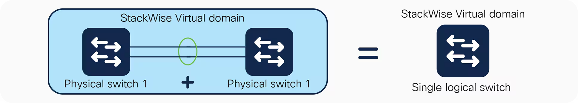
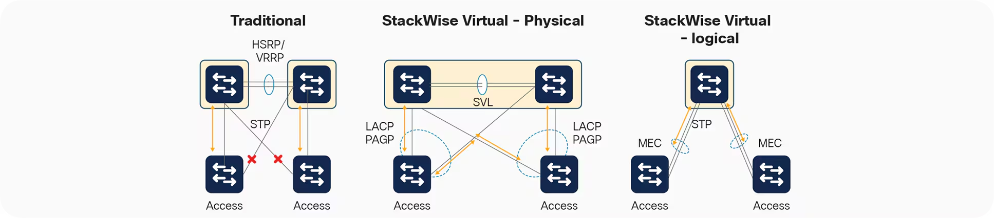
Images courtesy of Cisco.
Terms
SVL
Between 1 and 8 inter-chassis links, for control-plane and data-plane traffic.
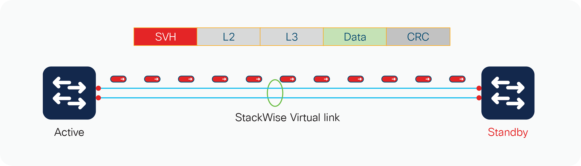
DAD
One worst case scenario, is the SVL fails, and both switches go Active/Active.
There are lot of bad effects from this:
- SVI IP Duplication
- SSH PKI Duplication
- STP Bridge ID Duplication
To help prevent this, it’s recommended to configure DAD links.
References
Products - Cisco Catalyst 9000 Platform StackWise Virtual White Paper - Cisco
Enterprise Campus Architecture
The C9000-L series, does not support Catalyst Center, and has lower StackWise speeds.
Two tier collapsed core
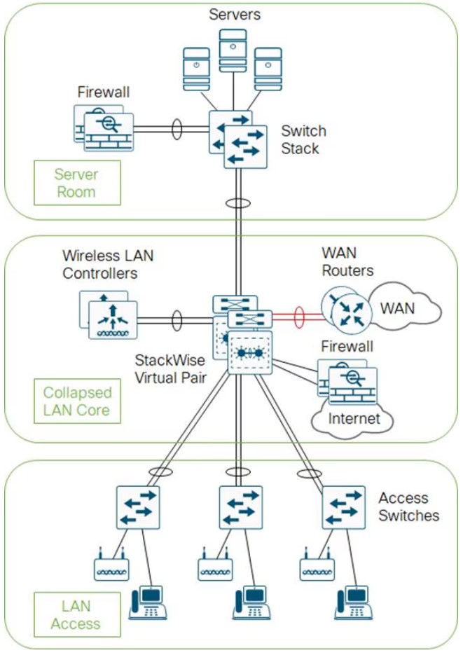
- The core and distribution switches are the same
- The center is running StackWise Virtual
Three tier
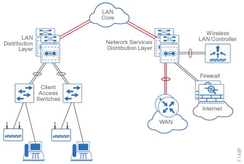
Layer 2 access with traditional multilayer
- Layer 2 is a single wiring closest, or access uplink pair.
- FHRP is used, but limits bandwidth to one uplink, vs both.
The campus network
- Campus networks are always oversubscribed.
- Over-subscription rates between 4-20 are common.
- Networks with over-subscription that results in queuing should implement QoS for voice traffic.
Core layer
Fast and expensive.
Gear
- 9500
- 9600 (modular chassis)
Features
- No services
- Layer 3 only
- Always on
- Ideally, a minimum of 100G to conserve ports.
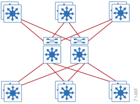
Distribution layer considerations
Purpose
-
Aggregates wiring closets.
-
Protects the core from high-density peering, and access layer problems.
-
Summarize routes towards core
-
Set STP root to be the FHRP Primary
-
Enable
- RootGuard on Downlinks
- Loopguard on Uplinks
-
Disable
- DTP
Gear
- 9400 (modular chassis)
- 9500
- 9600 (modular chassis)
Features
- Service heavy (FHRPs, Routing, SVIs)
- Typical L2 boundary
- Used to interconnect all the access layer switches in a building
- Used to interconnect Access layer switches, once they can’t form a full-mesh
- Also contains the failure domain of the access layer.
- Simplified Distribution, using StackWise Virtual to remove FHRP.
Access layer
Set ports to access ports.
-
Disable
- DTP
-
Enable
- Portfast
- BPDU Guard
- Use Root Guard on designated ports toward downstream switches when the port should participate in STP, but must not accept a superior BPDU
Gear
- 9200 (160Gbps stack-wise ring)
- 9300 (480Gbps stack-wise ring)
- 9400 (modular chassis)
Features
- Switch stacking
- Also provides HA
- POE
- Perpetual Power (survives reboots)
- mGig (Access port speed scaling)
- Port Security
- 802.1x
- Dynamic ARP Inspection
- DHCP Snooping
- Phones
- QoS
- Trust Boundaries
- Auxiliary VLANs
- IP Multicast
- IGMP snooping
- Link Aggregation
- LACP/PAGP
Traditional design
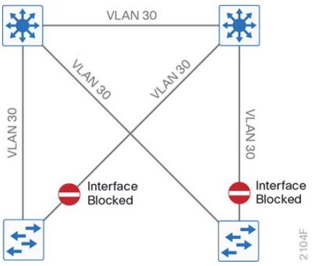
- Needs STP to block ports
- VLANS can span multiple switches.
Traditional design - loop free
- This relies on SVI Autostate.
- VLANs cannot span multiple switches.
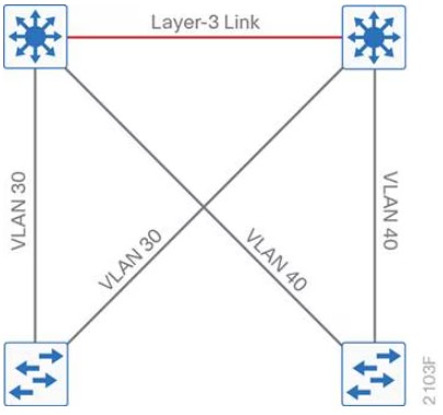
Other designs
SD-Access
- Cisco Catalyst Center
- Cisco Identity Services Engine
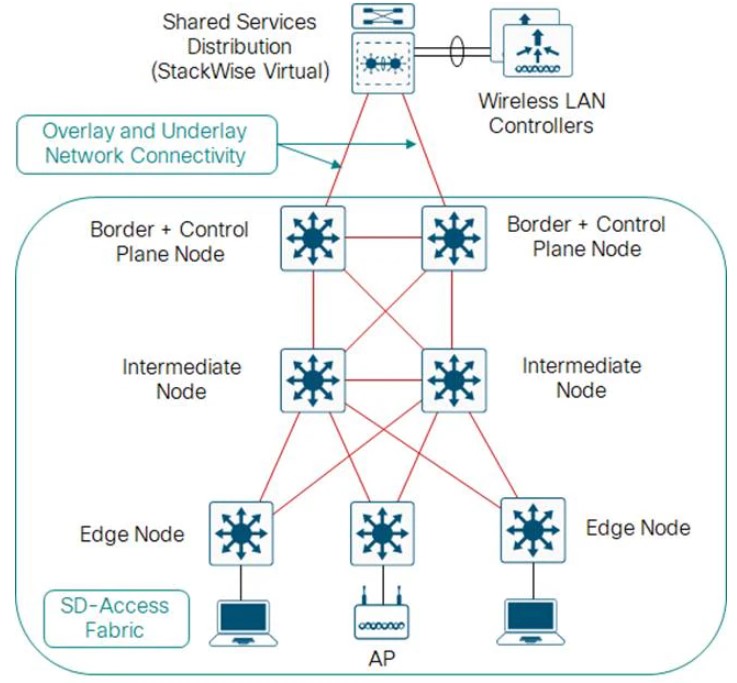
Open standards based overlay
- MP-BGP
- VXLAN
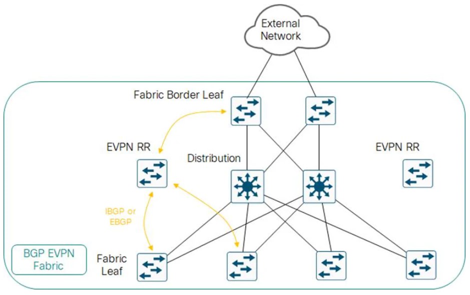
Campus LAN best practices - security
-
DHCP Snooping, to prevent users from hooking up a DHCP server from home on accident.
-
Dynamic ARP inspection, to prevent an ARP attack, where the attack sends ARP replies with the IPs in the subnet.
-
BPDU Guard, to prevent home switches from participating in spanning tree on edge ports.
-
802.1x, port authentication
-
Cisco Umbrella, Cisco’s DNS offering.
Campus LAN best practices - high availability
-
SSO: Stateful Switch Over, used to sync RPs in modular switches.
-
NSF: Non-Stop Forwarding allows graceful restarting of a L3 protocol. Allows the data-plane to continue while the new RP
-
MLS: Multi-layer Switch.
-
StackWise: Older tech, to combine switches together. Up to 8 switches can be stacked. They operate as one switch.
-
StackWise Virtual: Two MLS devices, are combined to become one logical device.
-
StackWise Virtual Link: The control/data path between the two switches. Should be two links minimum.
-
GIR: Graceful Insertion or Removal. Influencing paths by changing route-metrics or adjusting FHRP priorities.
Etherchannel
- Use a dynamic protocol, to check on link health
References
Design Zone - Campus LAN and Wireless LAN Solution Design Guide - Cisco
Enterprise Campus Design - Multilayer Architectures and Design Principles - Cisco Live 2023
Enterprise Campus Modular Design
Connections shown are logical to connect the modules, not the actual connections :)
Cisco AAA
aaa new-model
Local database
Is usually the fallback.
Basic config
!
! The Radius Server
!
radius server RADIUS-UCS-1
address ipv4 10.0.0.1 auth-port 1812 acct-port 1813
key StrongPassword123
!
! default means, "Apply to Everything, including console."
!
aaa authentication login default group radius local
!
! This is the localfallback method
!
username admin privilege 15 secret 9 $9$BXZm9X.AvojmtP$LlbzicXZ..f7Y/J59M4cgmTMCdh89fVZj6AyaOYleCg
Config for the AAA server
AAA servers are sensitive to what IP is making the request. To make it easier, pick a loopback.
ip radius source-interface, or ip tacacs source-interface
Debugs
debug aaa authentication
debug radius authentication
debug tacacs authentication
debug aaa protocol local
TACACS+
Terms
RADIUS — Remote Authentication Dial-In User Service.
Created to provide AAA for ISP users, or Dial-In for businesses.
TACACS — Terminal Access Controller Access-Control System.
An AAA protocol to provide support for authenticate once, authorize many.
TACACS+
Same as above, basically an upgraded version, not backward compatible.
EAP — Extensible Authentication Protocol
802.1x, used for LAN Auth, only works with RADIUS.
TACACS+ authentication messages
sequenceDiagram
participant T as Terminal User
participant C as AAA Client
participant S as AAA Server
T ->> C: Admin Session
C ->> S: START (Authentication) - User Trying to Connect
S -->> C: REPLY (Authentication) - Request Username
C ->> S: CONTINUE (Authentication) - Username
S -->> C: REPLY (Authentication) - Request Password
C ->> S: CONTINUE (Authentication) - Password
S -->> C: REPLY (Authentication) - Pass
Note over C: Authentication Complete
TACACS authorization and accounting messages
sequenceDiagram
participant T as Terminal User
participant C as AAA Client
participant S as AAA Server
Note over C: Authentication Complete
C ->> S: REQUEST (Authorization) – Service = Shell
S -->> C: RESPONSE (Authorization) – PASS_ADD
C ->> S: REQUEST (Accounting) – START
S -->> C: RESPONSE (Accounting) – SUCCESS
T ->> C: #35; show run
C ->> S: REQUEST (Authorization) – Service = Command
S -->> C: RESPONSE (Authorization) – Pass_ADD
C ->> S: REQUEST (Accounting) – CONTINUE
S -->> C: RESPONSE (Accounting) – SUCCESS
References
A. Woland, V. Santuka, J. Sanbower, and C. Mitchell, Integrated Security Technologies and Solutions – Volume II: Cisco Security Solutions for Network Access Control, Segmentation, Context Sharing, Secure Connectivity, and Virtualization. Hoboken, NJ, USA: Cisco Press, 2019, ISBN 978-1-58714-707-4.
Clouds
Most of this is based on the NIST definitions.
NIST characteristics
On-Demand
- Unilateral, no human interaction
Broad Network Access
- Works on phones, laptops, desktops
Resource Pooling
- Multi-tenant
- Location independence
Rapid Elasticity
-
Capabilities can be provisioned and released, in some cases automatically
-
Resources often appear unlimited
-
Scales with demand
Measured Service
- Resource usage is monitored controlled and reported
Service models
SaaS — Software as a Service
Running a providers app on their cloud infrastructure.
- Microsoft 365 (MS Teams)
- Salesforce (CRM)
- Atlassian (Agile)
- Adobe Creative Cloud
PaaS – Platform as a Service
Deploy your own apps into a cloud.
-
AWS: Elastic Beanstalk (Java, Python etc.)
-
Azure App Service
-
Google App Engine
-
IBM Cloud Foundry
IaaS — Infrastructure as a Service
Provision compute, storage, and networks on a providers cloud network.
- AWS (Amazon)
- Azure (Microsoft)
- Google Cloud Platform
Deployments
Private
- Provisioned exclusively for one organization
- The organization can have multiple customers
- Can be on or off premise
Community
- Provisioned exclusively for a community with a shared concern
- Mission based
- Security requirements
- Policy Requirements
- Compliance Requirements.
An example is is credit unions.
Public
Open for use by the public.
Hybrid
Merging some private cloud resources, with a public cloud offering.
- Adding AI capability.
References
800-145 The NIST Definition of Cloud Computing
Apache - Configuring a Virtual Private Cloud
What is Amazon VPC? - Amazon Virtual Private Cloud
VPCs
A VPC is a tenant scoped cloud network construct.
VMs inside a VPC can usually communicate with the outside world via NAT, but need some kind of public IP to be reachable from the Global Internet.
Google’s VPC is implemented with Andromeda.
Terms
VM — Virtual Machine
- Essentially a computer
VPC — Virtual Private Cloud
- Connects VMs
- Subnets
- IP Addresses
- Route Tables
- Network Connections
- Peering
- Traffic Mirroring
- Internet Gateway
- VPC Peering
- NAT Gateway
References
Apache - Configuring a Virtual Private Cloud
Microsoft - What is Azure Virtual Network?
Google - VPC networks | Virtual Private Cloud
Cloud Interconnects
- AKA, Middle Mile Optimization
SDCI connections generally have 99.999% availability.
Provisioning two WAN Edges in a SDCI provider creates a SDCI.
The WAN edges are IGs.
Terms
POP — Point of Presence
- The business has their network in the building
SDCI — Software Defined Cloud Interconnects
IG — Interconnect Gateway
Example
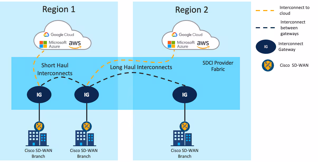
Image courtesy of Cisco.
References
Gartner - SDCI reviews and Ratings
Cisco - SDWAN Configuration Guide - IOS-XE 17.x - Cloud OnRamp for Multicloud: Cloud Interconnect
Cisco - SDWAN Configuration Guide - IOS-XE 17.x - Cloud OnRamp for Multicloud: SDCI with Megaport
NetworkAcademy.IO - The Overlay Fabric
FHRP
Useful for hosts, which cannot configure more than one IP.
FHRPs can suffer from asymmetrical routing, if two switches advertise the same subnet, upstream equipment cannot know which switch is the primary.
This is generally not a problem if both switches can still reach both hosts, but becomes a problem with spanning tree blocking ports.
Terms
FHRP — First Hop Redundancy Protocol
VIP — The IP intended for hosts provided by the FHRP.
References
First-hop redundancy protocol - Wikipedia
Network Services Configuration Guide, Cisco IOS XE 17.x - Configuring VRRP Cisco IOS XE 17 - Cisco
RFC 9568: Virtual Router Redundancy Protocol (VRRP) Version 3 for IPv4 and IPv6 | RFC Editor
VRRP
VRRP is currently in version 3, it’s a standards based way to perform FHRP.
- Active Router
- The router performing as the default gateway
- Backup Router
- The routers waiting to transition to become default gateways.
Details
- Default timers: 1s / 3 seconds
- 224.0.0.18
Example
R5# show vrrp brief
Interface Grp Pri Time Own Pre State Master addr Group addr
Gi0/0 56 100 3609 Y Backup 192.168.56.6 192.168.56.56
Config
interface GigabitEthernet0/0
ip address 192.168.56.5 255.255.255.0
ipv6 address 2001:DB8:0:56::5/64
vrrp 56 ip 192.168.56.56
References
Network Services Configuration Guide, Cisco IOS XE 17.x - Configuring VRRP Cisco IOS XE 17 - Cisco
RFC 9568: Virtual Router Redundancy Protocol (VRRP) Version 3 for IPv4 and IPv6 | RFC Editor
GLBP
This is a Cisco proprietary FHRP. The v4 and v6 exist for IOS, but v6 is missing for IOS-XE.
Terms
GLBP — Gateway Load Balancing Protocol
- Cisco Proprietary
- Supports 4 active forwarding instances
AVG — Active Virtual Gateway
- The AVG is responsible for answering incoming ARP for the VIP
- Can reply with a different MAC addresses to load balance
- Highest priority router is the AVG
AVF — Active Virtual Forwarder
- Two states {Active, Listen}
- All AVFs have their own mac and forwarding traffic destined towards that MAC
- 4 max
Details
- Multicast
- 224.0.0.102
- UDP 3222
- MD5 is supported
- Default timers: 3s / 10s
Example
R1# show glbp brief
Interface Grp Fwd Pri State Address Active router Standby router
Gi0/0 12 - 100 Active 192.168.12.12 local 192.168.12.2
Gi0/0 12 1 - Active 0007.b400.0c01 local -
Gi0/0 12 2 - Listen 0007.b400.0c02 192.168.12.2 -
Config
interface GigabitEthernet0/0
ip address 192.168.12.1 255.255.255.0
!
glbp 12 ip 192.168.12.12
glbp 12 priority 100
glbp 12 preempt
!
glbp 12 weighting 100
glbp 12 load-balancing round-robin
References
Solved: Re: ASR-1002X IPv6 GLBP - Cisco Community
HSRP
Cisco Proprietary
- UDP port 1985 (v6 2029)
- Version 1, RFC 2281
- Version 2, adds IPv6, no RFC
Version 1
- No millisecond timers
- Groups from 0 to 255
- hello messages have virtual mac
- 224.0.0.2
- default timers: 3s / 10s
Version 2
- Millisecond timers
- Groups from 0 to 4095
- Hello messages have src-mac
- 224.0.0.102
- ff02::66
- address range: 0000.0C9F.F000 to 0000.0C9F.FFFF
Example
R3# show standby brief
P indicates configured to preempt.
|
Interface Grp Pri P State Active Standby Virtual IP
Gi0/0 34 100 Standby 192.168.34.4 local 192.168.34.34
Config
interface GigabitEthernet0/0
ip address 192.168.34.3 255.255.255.0
standby 34 ip 192.168.34.34
ipv6 address 2001:DB8:0:34::3/64
References
Hot Standby Router Protocol - Wikipedia
ACLs
- Stop on first match.
- end-of-list, no matches, deny.
An ACL to just count traffic should always end with
permit ip any any
Block a specific host
Necessary because the default action at the end is “deny any”
access-list 1 deny host 10.0.0.1
access-list 1 permit any
Allow a host range
This allows packets from 192.168.10.0/24 to travel to 192.168.200.0/24
access-list 101 permit ip 192.168.10.0 0.0.0.255 192.168.200.0 0.0.0.255
Deny access except from specific hosts
Usually required for features like CoPP
access-list 10 permit 10.0.0.1
access-list 10 permit 10.0.0.2
access-list 10 permit 10.0.0.3
References
CoPP with ACLs and Object Groups
This was performed on an C8000v, running 17.13.1a
A simple ACL that matches based on ICMP.
!
! Access List
!
ip access-list extended ACL_ICMP_UNKNOWN
permit icmp any any
!
! Class-map to use the ACL.
!
class-map CLASS_MAP_ICMP_UNKNOWN
match access-group name ACL_ICMP_UNKNOWN
!
! Make a policy map that uses the above class-maps
!
policy-map POLICY_MAP_COPP
class CLASS_MAP_ICMP_UNKNOWN
police cir 10000 conform-action transmit exceed-action drop
class class-default
Apply it to the control plane.
control-plane
service-policy input POLICY_MAP_COPP
- Validate
router# show policy-map control-plane input
Control Plane
Service-policy input: POLICY_MAP_COPP
Class-map: CLASS_MAP_RFC1918 (match-all)
0 packets, 0 bytes
5 minute offered rate 0000 bps
Match: access-group name ACL_RFC1918
Class-map: CLASS_MAP_ICMP_UNKNOWN (match-all)
0 packets, 0 bytes
5 minute offered rate 0000 bps, drop rate 0000 bps
Match: access-group name ACL_ICMP_UNKNOWN
police:
cir 1000000 bps, bc 31250 bytes
conformed 0 packets, 0 bytes; actions:
transmit
exceeded 0 packets, 0 bytes; actions:
drop
conformed 0000 bps, exceeded 0000 bps
Class-map: class-default (match-any)
0 packets, 0 bytes
5 minute offered rate 0000 bps, drop rate 0000 bps
Match: any
Test setup
This uses python3, scapy, and sendpfast, to send icmp packets with random sources.
- Install sendpfast
sudo apt install tcpreplay
- Start a python virtual environment.
python3 -m venv venv
source venv/bin/activate
- Install scapy inside it.
pip install scapy
- Modify then paste in the following python script.
dst
iface
cat > flood.py << 'EOF'
from scapy.all import *
import random
def random_public_ip():
while True:
ip = f"{random.randint(1,223)}.{random.randint(0,255)}.{random.randint(0,255)}.{random.randint(1,254)}"
if not (ip.startswith("10.") or
ip.startswith("192.168.") or
ip.startswith("172.") and 16 <= int(ip.split(".")[1]) <= 31):
return ip
pkts = [Ether()/IP(src=random_public_ip(), dst="192.168.52.198")/ICMP() for _ in range(1000)]
sendpfast(pkts, pps=10000, loop=100, iface="ens18")
EOF
- In a different terminal run something like this to see the packets leaving the interface.
sudo tcpdump -i ens18 icmp -n
- This requires raw sockets to run.
sudo venv/bin/python3 flood.py
NAT
We specify an inside and outside network, so we can do one or both transforms.
Source NAT
Modifies the SA (Source address)
Destination NAT
Modifies the DA (Destination Address)
Translation
INSIDE NETWORK OUTSIDE NETWORK
┌────────────────────────────────────┐ ┌──────────────────────────────────────┐
│ │ │ │
│ ┌────────────┬─────────────┐ │ │ ┌─────────────┬──────────────┐ │
│ ────► │ SA │ DA │ │ ────► │ ────► │ SA │ DA │ │
┌──────┐ │ │Inside Local│Outside Local│ │ │ │Inside Global│Outside Global│ │ ┌───────┐
│Inside│ │ └────────────┴─────────────┘ │ ┌───┐ │ └─────────────┴──────────────┘ │ │Outside│
│ Host │ │ │ │NAT│ │ │ │ Host │
└──────┘ │ ┌────────────┬─────────────┐ │ └───┘ │ ┌─────────────┬──────────────┐ │ └───────┘
│ │ SA │ DA │ │ │ │ SA │ DA │ │
│ │Inside Local│Outside Local│ ◄──── │ ◄──── │ │Inside Global│Outside Global│ ◄──── │
│ └────────────┴─────────────┘ │ │ └─────────────┴──────────────┘ │
│ │ │ │
└────────────────────────────────────┘ └──────────────────────────────────────┘
Based on a diagram here.
NAT overload - port address translation or PAT
This is Source NAT.1
Packets to R3 will appear to be from 10.0.0.2
!
! R1
!
interface Ethernet0/0
ip address 192.168.1.1 255.255.255.0
!
ip route 0.0.0.0 0.0.0.0 192.168.1.2
!
! R2
!
interface Ethernet0/0
ip address 192.168.1.2 255.255.255.0
ip nat inside
!
interface Ethernet0/1
ip address 10.0.0.2 255.255.255.0
ip nat outside
!
ip nat inside source list 1 interface Ethernet0/1 overload
!
ip access-list standard 1
10 permit 192.168.1.0 0.0.0.255
!
! R3
!
interface Ethernet0/1
ip address 10.0.0.3 255.255.255.0
!
ip route 0.0.0.0 0.0.0.0 10.0.0.2
R2 debugs during NAT
R2# debug ip nat 1
IP NAT debugging is on for access list 1
*Sep 16 21:32:21.386: NAT: Entry assigned id 4
*Sep 16 21:32:21.386: NAT*: ICMP id=5->1024
*Sep 16 21:32:21.386: NAT*: s=192.168.1.1->10.0.0.2, d=10.0.0.3 [17]
*Sep 16 21:32:21.387: NAT*: ICMP id=1024->5
*Sep 16 21:32:21.387: NAT*: s=10.0.0.3, d=10.0.0.2->192.168.1.1 [17]
R2# show ip nat translations
Pro Inside global Inside local Outside local Outside global
icmp 10.0.0.2:1024 192.168.1.1:5 10.0.0.3:5 10.0.0.3:1024
-
Source NAT, because the source address needs to be changed to access outside hosts. As packets move through the router, they will create entries for return packets. ↩
DNS
DNS uses TCP and UDP.
UDP is usually tried first.
TC — TrunCation
- Message was truncated due to length greater than permitted
RFC 2181 says “try again with TCP”
DNS resource records
| RR | Description |
|---|---|
| A | v4 IP Address |
| AAAA | v6 IP Address |
| CNAME | Alias or nickname. Secondary Name |
| MX | Email server |
| NS | DNS Server |
| PTR | Reverse Mapping of an IP. Used to find the host that “owns” the IP |
| SOA | Start of Authority. Which DNS server is authoritative for the zone. |
DHCP & DNS placement
Always in groups of at least two, this is a HA service.
Each module should have its own set of DHCP and DNS nodes.
| Location | DHCP | DNS |
|---|---|---|
| Enterprise / Campus / DC | Yes | Internal DNS |
| Enterprise / Remote / Branch | Yes | Internal DNS |
| Enterprise / Remote / DC | — | Internal and External DNS |
| Enterprise / Edge / DMZ | — | External DNS |
| Enterprise / Edge / WAN | — | — |
| Enterprise / Edge / VPN | — | — |
| SP / Edge | — | External DNS |
References
DNS and UDP truncation | APNIC Blog
RFC 1035: STD 13: Domain names - implementation and specification
RFC 2181: Clarifications to the DNS Specification | RFC Editor
Configure SSH on Cisco IOS
This should also work for IOS-XE.
aaa new-model is necessary for the login default line under the vty.
Config
aaa new-model
!
username ariadne secret passwordgoeshere
!
ip domain-name <domain-here>
!
crypto key generate rsa modulus 4096
!
ip ssh version 2
!
line vty 0 15
transport input ssh
login authentication default
Verification
R2# ssh -l ariadne 10.0.0.1
[banner message]
Password:
[banner message]
R1>
NTP
Modes
Client-Server
- AKA,
server
Time is one way, the clients get time from servers.
Symmetric Active/Passive
- AKA,
peer
Devices have a low-stratum primary reference, but if that primary reference goes down, they can use each other as backups.
Broadcast or multicast
-
AKA,
broadcast -
Same subnet
-
Not as accurate
Config
Provide NTP
!
! 7 is pretty low
!
! good practice is to bind this to a stable interface, like a loopback
!
!
ntp master 7
ntp source Loopback0
Get NTP from another server
!
! NTP should never rely on a single server.
!
! Even my home network relies on seven external NTP servers.
!
!
ntp server pool.ntp.org
A public config
Warning
Does your organization use time in a way that human lives depend on it being correct?
You shouldn’t “just get it off the Internet”
The NTP Pool is generally very high quality, but it is a service run by volunteers in their spare time.
Please talk to your equipment and service vendors about getting local and reliable service setup for you.
See also our terms of service.
We recommend time servers from Meinberg, but you can also find time servers from End Run, Spectracom and many others.
From Using pool.ntp.org.
From this list.
ntp server pool.ntp.org
ntp server time.nist.gov
ntp server time.cloudflare.com
ntp source <loopback-goes-here>
ntp peer <other-router-goes-here>
!
! NTP Master 7 ... if Internet connectivity is lost, and external NTP fails, this box can still serve NTP.
!
ntp master 7
References
Cisco - Best Practices for NTP
Cisco - NTP Configuration Guide - IOS XE 17
Power Over Ethernet
PSE — Power sourcing equipment
- A PoE Ethernet switch
PD — Powered Device
- A phone
PoE Splitter
- Use Ethernet as a power source for low power devices
PoE Extender
- Increases Ethernet’s data and power range beyond 100m
Passive PoE
- AKA Pre-standard PoE.
- Usually old installs
Endspan
- The switch is the PSE
Midspan
- The PSE is an injector and daisy chained into the Ethernet
Mode-A
- AKA Alt-A
- Deliver power on the data pairs of 10Base-T or 100Base-T. (pairs 2, 3)
Mode-B
- AKA Alt-B
- Deliver power on the spare pairs of 10Base-T or 100Base-T. (pairs 1, 4)
LLDP
- Link Layer Discovery Protocol
- The IEEE equivalent to CDP
- Used by IEEE PoE to request power
Important
Passive PoE
You must know and supply the correct voltage, there is no voltage or power negotiation.
As a table
| Type | IEEE Standard | Maximum Power from PSE | Supported Modes | Notes |
|---|---|---|---|---|
| Passive PoE | - | No Negotiation | ||
| PoE | 802.3af | 15.4W | Mode A or Mode B (2-pair) | |
| PoE+ | 802.3at | 30W | Mode A or Mode B (2-pair) | |
| Cisco UPOE | Superset of 802.3at | 60W | Mode A, Mode B, or 4-pair | Works over CDP |
| PoE++, AKA 4PPPoE | 802.3bt aka 4PPoE | 90W | Mode A, Mode B, or 4-pair | |
| Cisco UPOE+ | Superset of 802.3bt | 90W | Mode A, Mode B, or 4-pair | Works over CDP |
As a flowchart
graph TD;
Passive["Passive PoE"];
AF["802.3af — PoE \n (15.4W)"];
AT["802.3at — PoE+ \n (30W)"];
BT["802.3bt - PoE++ \n (90W)"];
UPOE["Cisco UPOE \n (60W)"];
UPOEP["Cisco UPOE+ \n (90W)"];
Passive --> AF;
AF --> AT;
AT --> |"Includes IEEE Standard \n adds 30W"| UPOE;
AT --> BT;
BT --> |"Includes IEEE Standard \n adds Cisco UPOE"| UPOEP;
Cisco’s chart
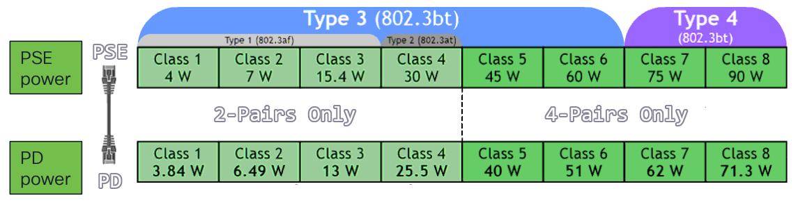
Wire example - 4 pairs
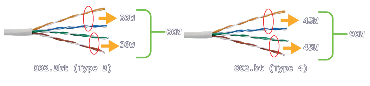
Power states
flowchart LR
A[Detection] --> B[Classification] --> C[Start to Power] --> D[Normal Power Supply]
References
Power over Ethernet - Wikipedia
Cisco - Industrial Power over Ethernet (PoE)
Cisco UPOE+- The Catalyst for Expanded IT-OT Convergence White Paper - Cisco
Cisco ECMP
BGP defaults to 1 path.
OSPF defaults to 4 paths.
EIGRP defaults to 4 paths.
ECMP algorithms
Your equipment might support different options.
Universal
- Default
- Selects based on (src-ip, dst-ip)
Original
- Legacy
- Exists on Cisco equipment
Tunnel
- Meant for tunnel endpoints
- Help with with low src-ip and dst-ip diversity
Include Ports
- Selects based on longer tuple
- (src-ip, dst-ip, src-port, dst-port)
ip cef load-sharing algorithm
References
Flexible NetFlow
Flexible Netflow needs four things to work:
- Records
- Exporters
- Monitors
- Interfaces
Config
IOS-XE
flow record FLOW_RECORD_IPV4
match ipv4 protocol
match ipv4 source address
match ipv4 destination address
match transport source-port
match transport destination-port
match interface input
collect interface output
collect counter bytes long
collect counter packets long
collect timestamp sys-uptime first
collect timestamp sys-uptime last
!
flow exporter FLOW_EXPORTER
!
! IPFix is standards based netflow.
!
export-protocol ipfix
destination 10.0.52.100
source GigabitEthernet2
transport udp 2055
template data timeout 60
!
flow monitor FLOW_MONITOR_IPV4
exporter FLOW_EXPORTER
cache timeout active 60
record FLOW_RECORD_IPV4
!
interface GigabitEthernet1
ip flow monitor FLOW_MONITOR_IPV4 input
ip flow monitor FLOW_MONITOR_IPV4 output
IOS-XR
flow exporter-map EXPORTER_MAP_1
version v9
options interface-table
template data timeout 600
!
dscp 48
transport udp 2055
source Loopback1
destination <IP 1>
!
flow monitor-map MONITOR_MAP_INTERNET
record ipv4
exporter EXPORTER_MAP_1
cache timeout active 60
cache timeout inactive 5
!
sampler-map SAMPLER_MAP_INTERNET
random 1 out-of 500
!
interface ten 1/1
flow ipv4 monitor MONITOR_MAP_INTERNET sampler SAMPLER_MAP_INTERNET ingress
flow ipv4 monitor MONITOR_MAP_INTERNET sampler SAMPLER_MAP_INTERNET egress
Lab validations
R1# show flow monitor FLOW_MONITOR_IPV4 statistics
Cache type: Normal (Platform cache)
Cache size: 200000
Current entries: 4
High Watermark: 4
Flows added: 8
Flows aged: 4
- Active timeout ( 60 secs) 4
R1# show flow monitor FLOW_MONITOR_IPV4 cache sort highest counter bytes long top 10 format table
Processed 3 flows
Aggregated to 3 flows
Showing the top 3 flows
IPV4 SRC ADDR IPV4 DST ADDR TRNS SRC PORT TRNS DST PORT INTF INPUT IP PROT intf output bytes long pkts long time first time last
=============== =============== ============= ============= ==================== ======= ==================== ==================== ==================== ============ ============
10.0.10.101 10.0.20.101 48640 5000 Gi4 17 Gi1 334100 325 20:37:12.210 20:37:44.424
10.0.12.2 224.0.0.5 0 0 Gi1 89 Null 600 6 20:36:54.026 20:37:41.568
10.0.12.1 224.0.0.5 0 0 Null 89 Gi1 600 6 20:36:52.808 20:37:38.836
AAA with FreeRadius and Univention UCS
This solution relies on:
- Univention UCS a Linux based, Active Directory, Domain Controller.
- FreeRADUS, an AAA plugin for Univention UCS.
Cisco side
AAA config
aaa new-model
!
radius server FREERADIUS
address ipv4 192.168.1.10 auth-port 1812 acct-port 1813
key StrongSharedSecret123
!
aaa authentication login default group radius local
!
aaa authorization exec default group radius local
!
line vty 0 15
login authentication default
transport input ssh
Univention UCS side
LDAP - create the groups
This loads the dc= stuff into ldap_base
eval $(ucr shell)
RADIUS Network Admins
udm groups/group create \
--position "cn=groups,$ldap_base" \
--set name="RADIUS Network Admins" \
--set description="Full RADIUS access to network devices"
RADIUS Network Read Only
udm groups/group create \
--position "cn=groups,$ldap_base" \
--set name="RADIUS Network Read Only" \
--set description="Read-only RADIUS access to network devices"
LDAP - verifying the groups
udm groups/group list --filter name="RADIUS Network Admins"
udm groups/group list --filter name="RADIUS Network Read Only"
Add users
Users need to be added to this group directly.
I am ariadne so that’s my uid.
udm groups/group modify \
--dn "cn=RADIUS Network Admins,cn=groups,$ldap_base" \
--append users="uid=ariadne,cn=users,$ldap_base"
Verify users
udm users/user list --filter uid=ariadne | grep -i group
FreeRADIUS clients
cat >> /etc/freeradius/3.0/clients.conf << 'EOF'
client internal_network {
ipaddr = 192.168.0.0/16
secret = StrongSharedSecret123
nas-type = cisco
}
EOF
FreeRADIUS Cisco AV pairs
eval $(ucr shell)
cat >> /etc/freeradius/3.0/mods-config/files/authorize << EOF
DEFAULT Ldap-Group == "cn=RADIUS Network Admins,cn=groups,$ldap_base"
Service-Type = NAS-Prompt-User,
cisco-avpair = "shell:priv-lvl=15"
DEFAULT Ldap-Group == "cn=RADIUS Network Read Only,cn=groups,$ldap_base"
Service-Type = NAS-Prompt-User,
cisco-avpair = "shell:priv-lvl=1"
DEFAULT Auth-Type := Reject
Reply-Message = "Not in any authorized group"
EOF
Testing on Cisco
test aaa group radius ariadne my-password legacy
Testing on UCS
radtest <user-in-ldap> <ldap-password> <server-ip> 0 <FreeRADIUS-secret>
Do packets arrive
tcpdump -i any -n udp port 1812
Debugging FreeRADIUS
systemctl daemon-reload
systemctl restart freeradius
systemctl status freeradius
freeradius -X
After it’s working, RSYNC it
rsync -av /etc/freeradius/3.0/clients.conf \
root@ucs-2:/etc/freeradius/3.0/clients.conf
rsync -av /etc/freeradius/3.0/mods-config/files/authorize \
root@ucs-2:/etc/freeradius/3.0/mods-config/files/authorize
References
Univention Corporate Server - Manual for users and administrators
SNMP
NMS — Network Management System
SNMP — Simple Network Management Protocol
- Protocol to exchange network device statistics
SNMP Agent
- Lives on network equipment
- Collecting and stores information in a MIB
- Does not store history
MIB — Management Information Base
- On-device SNMP database
- The schema for the database
- How the SNMP agent stores information
ITU — International Telecommunication Union
- UN agency responsible for international telecommunications
OID Tree
- An ITU, X.660 standardized tree
OID — Object identifier
- Node on an OID tree
- A standard MIB, defined by the IETF
- Not popular
Vendor MIB
- Contrast to the IETF MIB
- Vendors can create their own MIBs, attached to the Global OID tree
What is stored in MIBs
Device Statistics
- Uptime, packets sent, packets received, packets dropped
- Memory used, CPU used, temperature, fan-speed
Using SNMP to track CPU time
On the device, I run a normal command, and look at the outputs:
switch # show processes cpu | i util
CPU utilization for five seconds: 20%/0%; one minute: 21%; five minutes: 20%
I want to figure out how to get the switch to report the first value “20” for “CPU used in the last 5 seconds.”
- What MIB does a C3560CX support?
- I find the formal specification for the MIB somewhere on the vendor website:
CISCO-PROCESS-MIB (109) - Looking at the OID tree first I identify a possible leaf
cpmCPUTotal1minRev via 1.3.6.1.4.1.9.9.109.1.1.1.1.7
- Looking at the MIB itself, I make sure it’s a supported OID
- I search for
cpmCPUTotal1minRev
- I search for
I find this…
cpmCPUTotal1minRev OBJECT-TYPE
SYNTAX Gauge32 (0..100)
UNITS "percent"
MAX-ACCESS read-only
STATUS current
DESCRIPTION
"The overall CPU busy percentage in the last 1 minute
period. This object deprecates the object cpmCPUTotal1min
and increases the value range to (0..100)."
::= { cpmCPUTotalEntry 7 }
This is the OID leaf I’m going to query:
.1.3.6.1.4.1.9.9.109.1.1.1.1.7
written out it looks like this…
iso.org.dod.internet.private.enterprise.cisco.ciscoMgmt.ciscoProcessMIB.cpmCPU.cpmCPUTotalObjects.cpmCPUTotalTable.cpmCPUTotalEntry.cpmCPUTotal1minRev
… “how much CPU did this Cisco device use in the last 1 minute?”
OIDREF shows the SNMP world OID tree.
graph TD
dot["."]
dot --> iso["iso (1)"]
iso --> mem["mem (2)"]
iso --> org["org (3)"]
org --> dod["dod (6)"]
dod --> internet["internet (1)"]
internet --> mgmt["mgmt (2)"]
internet --> private["private (4)"]
mgmt --> mib["mib (1)"]
private --> enterprise["enterprise (1)"]
mib --> ip["IP (4)"]
mib --> tcp["TCP (6)"]
mib --> udp["UDP (7)"]
mib --> snmp["SNMP (11)"]
enterprise --> cisco["cisco (9)"]
cisco --> ciscoMgmt["ciscoMgmt (9)"]
cisco --> ciscoExperiment["ciscoExperiment (10)"]
cisco --> ciscoAdmin["ciscoAdmin (12)"]
ciscoMgmt --> ciscoIpMIB["ciscoIpMIB (101)"]
ciscoMgmt --> ciscoProcessMIB["ciscoProcessMIB (109) CISCO-PROCESS-MIB"]
ciscoMgmt --> ciscoMemoryPoolMIB["ciscoMemoryPoolMIB (48)"]
ciscoProcessMIB --> cpmCPU["cpmCPU (1)"]
cpmCPU --> cpmCPUTotalObjects["cpmCPUTotalObjects (1)"]
cpmCPUTotalObjects --> cpmCPUTotalTable["cpmCPUTotalTable (1)"]
cpmCPUTotalTable --> cpmCPUTotalEntry["cpmCPUTotalEntry (1)"]
cpmCPUTotalEntry --> cpmCPUTotal1minRev["cpmCPUTotal1minRev (7)"]
style mem fill:#ddd,color:#aaa,stroke:#ccc
style mgmt fill:#ddd,color:#aaa,stroke:#ccc
style mib fill:#ddd,color:#aaa,stroke:#ccc
style ip fill:#ddd,color:#aaa,stroke:#ccc
style tcp fill:#ddd,color:#aaa,stroke:#ccc
style udp fill:#ddd,color:#aaa,stroke:#ccc
style snmp fill:#ddd,color:#aaa,stroke:#ccc
style ciscoExperiment fill:#ddd,color:#aaa,stroke:#ccc
style ciscoAdmin fill:#ddd,color:#aaa,stroke:#ccc
style ciscoIpMIB fill:#ddd,color:#aaa,stroke:#ccc
style ciscoMemoryPoolMIB fill:#ddd,color:#aaa,stroke:#ccc
style ciscoProcessMIB fill:#1a4a6b,color:#fff,stroke:#1a4a6b
Configs
SNMP v2
snmp-server community SSG_PROMETHEUS ro
SNMPv3
snmp-server group SSG_PROMETHEUS v3 priv
snmp-server user ciscosnmp SSG_PROMETHEUS v3 auth sha auth-password-goes-here priv aes 128 encryption-password-goes-here
Verify
These are performed on a linux host. This is apt install snmp on Debian.
SNMPv2
snmpwalk -v2c -c <community> <host> 1.3.6.1.4.1.9.9.109.1.1.1.1.7
SNMPv3
snmpwalk -v3 -l authPriv -u <user> -a SHA -A <auth-password> -x AES -X <encryption-password> <host> 1.3.6.1.4.1.9.9.109.1.1.1.1.7
ariadne@tesseract:~$ snmpwalk -v3 -l authPriv -u ciscosnmp -a SHA -A <removed> -x AES -X <removed> <host> 1.3.6.1.4.1.9.9.109.1.1.1.1.7
iso.3.6.1.4.1.9.9.109.1.1.1.1.7.1 = Gauge32: 20
Trap severity
snmp-server enable traps syslog
logging snmp-trap emergencies
logging snmp-trap alerts
logging snmp-trap critical
Is SNMP to configure devices
Nope. See RFC 3535.
SNMP works reasonably well for device monitoring. The stateless nature of SNMP is useful for statistical and status polling.
Refereces
How to find the MIB for Cisco Devices - GitHub
SNMP Versions
SNMPv1
- Cleartext
- Uses a community string for a basic password
Changing the equipment
- Set Request
Getting outputs
- Get Request
- GetNext
Receiving outputs
- Get Response
- Trap
SNMPv2
- Cleartext
- Uses a community string for a basic password
New message types
- Get Bulk (get lots of things)
- Inform Request (acknowledge this bad thing happening)
SNMPv3
This is the recommended version to make changes via SNMP.
| Security Level | Authentication | Encryption | Credentials Required |
|---|---|---|---|
| NoAuthNoPriv | None | None | Username only |
| AuthNoPriv | Yes | None | Username + Auth password |
| AuthPriv | Yes | Yes | Username + Auth + Priv password |
SNMP is Dead
The problem
SNMP doesn’t timestamps data
Polling the same OID, multiple times, leads to the same data.
There is always a delay between the counters, and when the SNMP agent scrapes the counter to add to the MIB.
The delay between the counter and the MIB update can be 30 to 60 seconds behind.
We never see real-time data.
Timeouts
SNMP frequently fails to return anything at all, even under modest load conditions.
When the data is graphed, the most impactful data (the spikes) will not show up, because the SNMP agent didn’t return a result.
The resulting graph is missing vital data.
SNMP is bad at low-latency updates
- Polling is asynchronous
- Over-polling leads to more load
- Traps are UDP and get lost
- Fast events like an interface flap are unnecessarily difficult to detect
SNMP doesn’t scale
- Modern RIBs are cannot be transmitted via SNMP.
The solution
Streaming Telemetry.
References
SNMP is Dead - Carl Lebsack, Rob Shakir - NANOG73
RMON
RMON — Remote Network Monitoring
- Extends the SNMP protocol
- Intended for network segments
- Intended for network traffic
RMON monitors are called probes.
RMON can monitor service quality.
We can define ahead of time thresholds for the equipment to alert at.
This is useful for SLAs.
Image courtesy of Juniper Networks.
RMON1 MIB
- Focused on OSI layers 1 & 2
| Group | Description |
|---|---|
| Statistics | Real-time LAN statistics e.g. utilization, collisions, CRC errors |
| History | History of selected statistics |
| Alarm | Definitions for RMON SNMP traps to be sent when statistics exceed thresholds |
| Hosts | Host specific LAN statistics e.g. bytes sent/received, frames sent/received |
| Hosts Top N | Record of N most active connections over a given time period |
| Matrix | The sent-received traffic matrix between systems |
| Filter | Defines packet data patterns of interest e.g. MAC address or TCP port |
| Capture | Collect and forward packets matching the Filter |
| Event | Send alerts (SNMP traps) for the Alarm group |
| Token Ring | Extensions specific to Token Ring |
RMON2 MIB
- Focused on OSI Layers 3-7
| Group | Description |
|---|---|
| Protocol Directory | List of protocols the probe can monitor |
| Protocol Distribution | Traffic statistics for each protocol |
| Address Map | Maps network-layer (IP) to MAC-layer addresses |
| Network-Layer Host | Layer 3 traffic statistics, per each host |
| Network-Layer Matrix | Layer 3 traffic statistics, per source/destination pairs of hosts |
| Application-Layer Host | Traffic statistics by application protocol, per host |
| Application-Layer Matrix | Traffic statistics by application protocol, per source/destination pairs of hosts |
| User History | Periodic samples of user-specified variables |
| Probe Configuration | Remote configure of probes |
| RMON Conformance | Requirements for RMON2 MIB conformance |
References
Monitor Network Service Quality by using RMON | Junos OS | Juniper Networks
RFC 2819: Remote Network Monitoring Management Information Base | RFC Editor
RFC 4502: Remote Network Monitoring Management Information Base Version 2 | RFC Editor
SD-WAN
Terms
DIA — Direct Internet Access
- Commodity Internet
MPLS — Multi-protocol Label Switching
- A private network provided by an ISP.
- Expensive and fast.
BFD — Bidirectional Forwarding Detection
SD-WAN policy
Policies are further classified as
- Local Policy: Programed on the edges. ACLs, QoS, routing, and AAA.
- Centralized Policy: Route policy, before being sent to the edges, (Topology, VPN Membership, Application Aware Routing)
Application aware routing
AAR — Application Aware Routing
FEC — Forward Error Correction
- Every four packets, send a parity packet
Packet Duplication
- Send twice as much data via two tunnels
- The receiving vEdge router can reconstruct it
TCP Optimization and Session Persistence
- High-latency links: satellite
- Open one TCP session
- Proxy
- Reuse
- Never drop
DRE — Data Redundancy Elimination
- Modern compression
- WAN links
vQoE — Viptela Quality of Experience
- AAR, or CoR
- Edge sends HTTP probes to measure jitter and/or loss
- 0 to 10, 10 being best
VPNs
VPNs go from 0 to 65530.
Some VPNS are already used.
VPN 0
The Underlay, transport VPN. All the dTLS connections live here.
VPN 512
OOB Management. This VPN isn’t carried across the dTLS connections.
SDWAN analytics
-
Application Experience
- Application Use
-
Site Health
- Tunnel Health
-
Bandwidth Forecasting
- Capacity Planning
-
Talos Integration
- Threat Mitigation
Default permissions groups
Basic
Can view the system.
Operator
Can view the system.
Netadmin
Can perform all operations
Commands
!
! Control Setup
!
show sdwan control local-properties
show sdwan control connections
show sdwan control connection-history
!
! OMP
!
show sdwan omp peers
show sdwan omp routes
show sdwan omp tlocs
show sdwan omp services
show sdwan omp summary
show sdwan omp multicast-routes
!
! Validator
!
show orchestrator connections
References
Cisco Live - Empowering your Network with SDWAN OMP - Waqas Daar - BKRENT-3115
Cisco Live - SD-WAN Start Here - Lars Granberg - BRKENT-2108
Network Academy - SDWAN Deep-Dive
Cisco Community - Cisco SDWAN Webinar
Cisco - Design Zone for Branch/WAN - SDWAN Design Guide
Cisco - SDWAN User Documentation
Cisco - SDWAN High Availability Configuration Guide, IOS-XE 17
Cisco - Youtube - SD-WAN: Multicloud Overview and Demonstration
SD-WAN OMP
Terms
OMP — Overlay Management Protocol
graph LR
subgraph OMP["Overlay Management Protocol"]
OMP-Routes(["OMP Routes"])
TLOC(["Transport Locators"])
SERVICE(["Service Routes"])
end
OMP routes
- AKA, vRoutes
- AKA, Site prefixes
10.0.0.0/24 - Static, OSPF or BGP
TLOC — Transport Locator
-
Each TLOC will attempt a full-mesh connection with every other TLOC
- Full Mesh
-
Tunnel endpoint is a 3-tuple
-
System IP,
-
Color
-
Encapsulation
-
Service Routes
- Embedded network services at the local-site
- Firewalls
- IPS
Full Mesh Equation
\[ \frac{N(N-1)}{2} \]
TLOC route attributes
- Private Address
- Public Address (the NAT translated address)
- Carrier (public or private)
- Color
- Encapsulation of tunnel
- GRE, IPSec
- Preference
- Site ID
- Tag
- Weight
OMP route attributes
OMP routes require OMP peering.
All OMP routes have TLOC associated.
show sdwan omp peers
These require a TLOC.
- TLOC
-System IP of the speaker who Originates the route
- Color
- Encapsulation of Tunnel
- System IP
- Origin
- BGP
- OSPF
- Static
- Connected
- Originator
- Preference (Higher is more preferred)
- Tag
- VRF
OMP preference
- Can it resolve?
- Route Preference (Intra region > core region. Prefer TR-sourced or ECMP.)
- TLOC Preference.
- Origin Type (Connected > Static > eBGP > EIGRP Internal > OSPF Intra > OSPF Inter > OSPF External > EIGRP External> iBGP)
- Origin Metric (lowest)
- Route Source (prefer route from vEdge, over vSmart)
- Lowest System IP
- Highest Private TLOC IP from the same site-id.
Example network
- Prefer the biz-internet connections.

TLOC
| TLOC (System IP) | Color | Encap | Site ID | Preference | Originator |
|---|---|---|---|---|---|
| 10.0.0.1 | mpls | GRE | 100 | 0 | 10.0.0.1 |
| 10.0.0.1 | biz-internet | IPsec | 100 | 100 | 10.0.0.1 |
| 10.0.0.2 | mpls | GRE | 100 | 0 | 10.0.0.2 |
| 10.0.0.2 | biz-internet | IPsec | 100 | 100 | 10.0.0.2 |
| 10.0.0.10 | mpls | GRE | 200 | 0 | 10.0.0.10 |
| 10.0.0.10 | biz-internet | IPsec | 200 | 100 | 10.0.0.10 |
| 10.0.0.11 | mpls | GRE | 200 | 0 | 10.0.0.11 |
| 10.0.0.11 | biz-internet | IPsec | 200 | 100 | 10.0.0.11 |
OMP routes
| VPN | Prefix | Originator | TLOC (System IP, Color, Encap) | Origin | Metric | Site ID |
|---|---|---|---|---|---|---|
| 1 | 172.16.0.0/16 | 10.0.0.1 | 10.0.0.1, mpls, GRE | connected | 0 | 100 |
| 1 | 172.16.0.0/16 | 10.0.0.1 | 10.0.0.1, biz-internet, IPsec | connected | 0 | 100 |
| 1 | 172.16.0.0/16 | 10.0.0.2 | 10.0.0.2, mpls, GRE | connected | 0 | 100 |
| 1 | 172.16.0.0/16 | 10.0.0.2 | 10.0.0.2, biz-internet, IPsec | connected | 0 | 100 |
| 1 | 172.17.0.0/16 | 10.0.0.10 | 10.0.0.10, mpls, GRE | connected | 0 | 200 |
| 1 | 172.17.0.0/16 | 10.0.0.10 | 10.0.0.10, biz-internet, IPsec | connected | 0 | 200 |
| 1 | 172.17.0.0/16 | 10.0.0.11 | 10.0.0.11, mpls, GRE | connected | 0 | 200 |
| 1 | 172.17.0.0/16 | 10.0.0.11 | 10.0.0.11, biz-internet, IPsec | connected | 0 | 200 |
References
Cisco Live - Empowering your Network with SDWAN OMP - Waqas Daar - BKRENT-3115
LAB 1 - Hub-and-Spoke - Restricting spoke-to-spoke tunnels | NetworkAcademy.IO
Advanced SD-WAN Troubleshooting - Cisco Live
SD-WAN Node Types
Manager
- AKA vManage
- What a human interacts with, the GUI
- Speaks NETCONF to configure the other nodes
- AKA, the NMS
Validator
- AKA, vBond
- Initial Authentication and provisioning,
- Responsible for NAT traversal
- AKA, Orchestration
Should be give a FQDN, so WAN edges have no problems finding it on connection to a DIA.
FQDNs also mean we aren’t putting a static IP into a config.
Initial authentication is done with PKI, and RSA encryption.
Can not be placed behind NAT, unless the NAT device does a 1:1 static translation.
This device does the load balancing if multiple controllers are being used.
The Validator has a permanent dTLS tunnel to all the controllers.
Controller
- AKA vSmart
- Holds the current state of the network, (routes and data policy) maintains active connections to the edges and programs them.
- dTLS connections
- OMP towards the WAN Edge
- NETCONF towards the Manager
- dTLS connections
- Keeps all the routes between sites, that are managed via the OMP protocol (like BGP, but proprietary)
- Logical tunnel topologies (such as hub and spoke, regional, and partial mesh)
- Service Chaining
- Traffic Engineering
- Segmentation per VPN
sequenceDiagram
participant Edge as SD-WAN Edge
participant Control as SD-WAN Controller
rect rgba(0, 0, 255, .1)
note over Edge, Control: dTLS Tunnel
Edge <<->> Control: OMP
Edge <<->> Control: SNMP
Edge <<->> Control: Netconf
end
WAN edge
- AKA vEdge, AKA Viptela (legacy gear)
- Dataplane, and Onsite
- DIA, or MPLS.
- Has OMP, BGP, OSPF, EIGRP, ACLs, ARP, HA, and QoS
- Connects via dTLS to the controllers
- Connects via dTLS to other edges
References
Cisco Live - Empowering your Network with SDWAN OMP - Waqas Daar - BKRENT-3115
SD-WAN Multicast
Note
Data streams are forwarded to the receivers through replication.
Terms
Replicator
The FHR forwards the multicast stream to the replicator.
Multicast
- PIM-SM is supported
- the RP is one of the control nodes
- No Support for
- BIDIR-PIM
- MSDP
Flow
This is based on BRKENT-3115, slides 107-110.
sequenceDiagram
box rgba(33,150,243,0.10) Source / FHR Site
participant Source as Source
participant Edge1 as Edge 1<br/>FHR
end
box rgba(120,144,156,0.10) RP Site
participant RP as RP
participant Edge3 as Edge 3
end
box rgba(38,198,218,0.10) SD-WAN Fabric
participant RepA as Edge 4<br/>Replicator A
participant Ctrl as SD-WAN<br/>Controller
participant RepB as Edge 5<br/>Replicator B
end
box rgba(67,160,71,0.10) Site A
participant Edge2 as Edge 2<br/>LHR
participant RecvA as Receiver A
end
box rgba(255,167,38,0.10) Site B
participant Edge6 as Edge 6<br/>LHR
participant RecvB as Receiver B
end
Note over RP,RecvA: Phase 1 — Receiver-A (*,G) Towards RP
RecvA -->> Edge2: 1. IGMP Join (*,G)
Edge2 -->> Ctrl: 2. OMP Update<br/>Type 6 Join (*,G)
Ctrl -->> RepA: 3. OMP Update<br/>Type 6 Join (*,G)
RepA -->> Edge3: 4. OMP Update<br/>Type 6 Join (*,G)
Edge3 -->> RP: 5. PIM Join (*,G)
Note over Source,Ctrl: Phase 2 — Source Registration & (S,G)
Source -->> Edge1: 6. Multicast Traffic
Edge1 -->> Edge3: 7. PIM Register (unicast)
Edge3 -->> RP: 8. PIM Register
RP -->> Edge3: 9. PIM Join (S,G)
Edge3 -->> Ctrl: 10. OMP Update Type 7 Join (S,G)
Ctrl -->> RepA: 11. OMP Update Type 7 Join (S,G)
RepA -->> Edge1: 12. OMP Update Type 7 Join (S,G)
Note over Source,RecvB: Phase 3 — Source-Active fan-out + Receiver-B onto SPT
Edge1 -->> Ctrl: 13a. OMP Update Type 5 (S-A)
Note over Ctrl: 13b. Controller floods Type 5 (S-A) to ALL WAN edges
Ctrl -->> Edge2: 13b. Type 5 (S-A)
Ctrl -->> Edge3: 13b. Type 5 (S-A)
Ctrl -->> RepA: 13b. Type 5 (S-A)
Ctrl -->> RepB: 13b. Type 5 (S-A)
Ctrl -->> Edge6: 13b. Type 5 (S-A)
RecvB ->> Edge6: 14. IGMP Join (*,G)
Edge6 -->> Ctrl: 15. OMP Update Type 7 Join (S,G)
Ctrl -->> RepB: 16. OMP Update Type 7 Join (S,G)
RepB -->> Edge1: 17. OMP Update Type 7 Join (S,G)
Note over Source,RecvB: Phase 4 — Dataplane
Edge1 ->> RepA: Multicast (S,G) stream
RepA ->> Edge2: Replicated to LHR
Edge2 ->> RecvA: Multicast (S,G) stream
Edge1 ->> RepB: Multicast (S,G) stream
RepB ->> Edge6: Replicated to LHR
Edge6 ->> RecvB: Multicast (S,G) stream
References
Cisco Live - Empowering your Network with SDWAN OMP - Waqas Daar - BRKENT-3115
Routing Configuration Guide for vEdge Routers, SD-WAN Release 20 - Multicast - Cisco
SD-WAN Bootstrap
USB
Requirements
- Device must be unprovisioned
The Manager can create a bootable USB drive.
Paste method
This can be used to paste in a bootstrap so you can just erase and reload the device
tclsh
puts [open "bootflash:name-of-bootstrap-file.cfg" w+] {
!
! Certificates in the top of this file.
!
! Use a terminal client like SecureCRT
!
! Enable characters and line send delay if you need to.
!
}
Python webserver
This uses python to start a small webserver to copy the bootstrap via HTTP.
Requirements
- Python
- This small python oneliner gets your current v4 IP.
python -c "import socket; s = socket.socket(socket.AF_INET, socket.SOCK_DGRAM); s.connect(('8.8.8.8', 80)); print(s.getsockname()[0]); s.close()"
- Start the small http server
0.0.0.0 means bind on all IPs.
python -m http.server 8000 --bind 0.0.0.0
- Using the Cisco CLI, copy the file from your python webserver.
copy http://10.0.0.1:8000/bootstrap-file.cfg bootflash:/bootstrap-file.cfg
Cisco - SD-WAN Getting Started Guide
SD-WAN Cloud
Terms
CSP — Cloud Service Provider
Site to Cloud
- Deploy vEdge at CSP
- Connect vEdge to VPC
- Connect VPC to IaaS
Cloud Gateway
- One vEDGE per VPC
TGW — Transit Gateway
A CSP construct to connect multiple VPCs
- Azure is called vHUB
- Amazon is called TGW
SaaS
Used to pick network connections, or maybe even the overlay to use a different site.
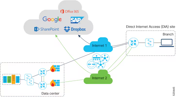
Image courtesy of
Cisco SD-WAN cloud OnRamp
- Figures out the best path and measures jitter
Cloud OnRamp for IAAS
- Transit VPC with two vEdges
- Transit VPC connects to other VPCs
- Cloud VPCs learned via BGP
- Redistributed into OMP
Used to interconnect devices within the Cloud.
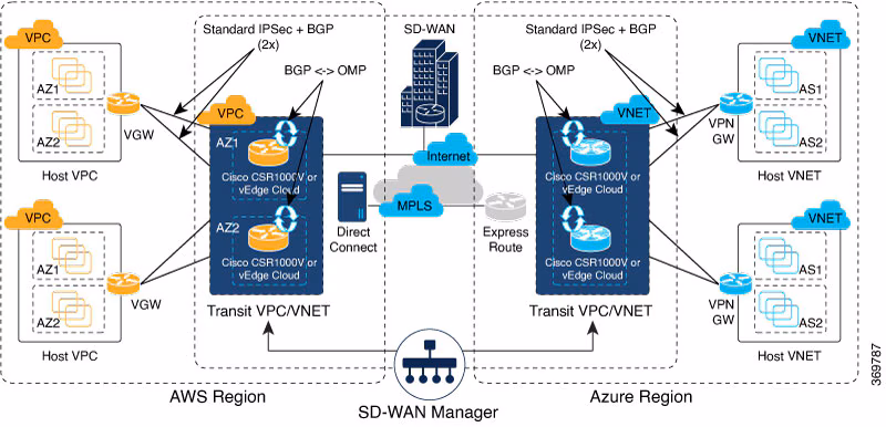
Image courtesy of
SDWAN multicloud
- TGW native
- Automation for instantiaton
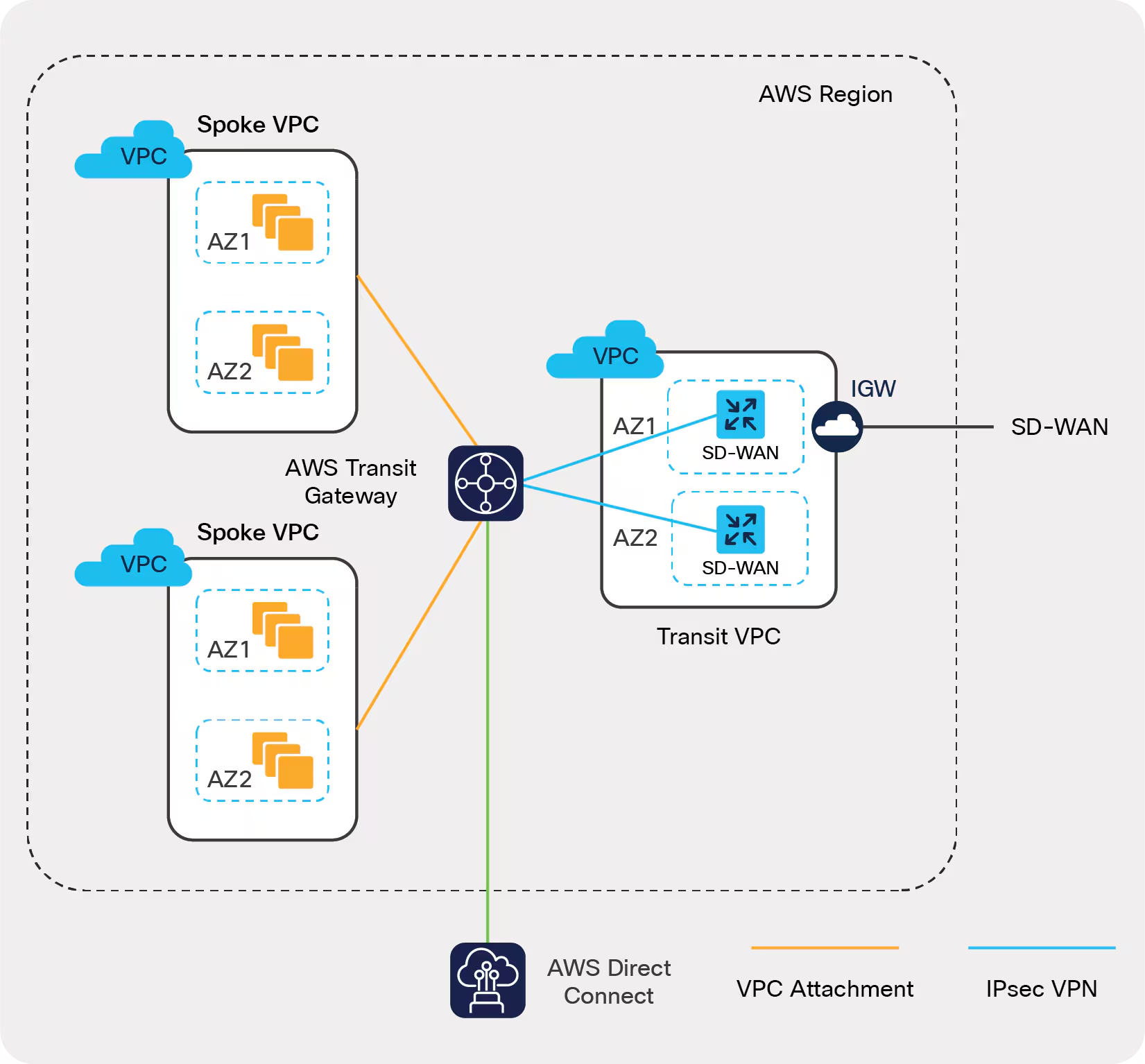
References
Cisco Live - SDWAN Cloud OnRamp for Multicloud BRKENT-2060
Cisco - Whitepaper - SDWAN Cloud OnRamp for IaaS
Cisco - SD-WAN Cloud Hub with Google Cloud At-a-Glance
SD-WAN Colors
Public colors are behind NAT.
| Public (NAT) | Private |
|---|---|
| public-internet | mpls |
| biz-internet | metro-ethernet |
| lte | private1 |
| 3g | private2 |
| blue | private3 |
| bronze | private4 |
| custom1 | private5 |
| custom2 | private6 |
| custom3 | |
| default | |
| gold | |
| green | |
| red | |
| silver |
Terms
Color is a Cisco shorthand for the type of connection the SD-WAN is attached to.
Private IP
- AKA Native IP
- AKA RFC 1918 address
Public IP
- AK, NAT address
Communication between colors
If two TLOCs try to make a tunnel, they will fall back to both using Public IPs, if either has a Public IP.
Public Private
Color Color
┌────────┬─────────┐
Public │ Public │ Public │
Color │ IPs │ IPs │
├────────┼─────────┤
Private │ Public │ Private │
Color │ IPs │ IPs │
└────────┴─────────┘
References
NetworkAcademy - TLOCs and NAT
Cisco - SDWAN Configuration Guide - IOS-XE 17.x - TLOCs
SD-WAN ZTP
Requirements
- Edge needs DHCP
- Edge gets added to the PNP portal
- Manager synced to the PNP portal
There is an air-gapped version of ZTP available on request.
-
Plug in Ethernet with DHCP.
-
Gets an IP, requests the A record for
ztp.viptela.com(could also beztp.localdomain) -
(matches device by serial number based on what was put into the PNP portal earlier)
-
Once the authentication of the vEdge is done, vEdge gets the IP address of vManage and vSmart given by vBond.
-
The vEdge gets authenticated by vManage and gets the System IP address.
-
vManage pushes the predefined configuration to vEdge and vSmart pushes the policy to vEdge.
-
vEdge gets successfully on boarded to the SD-WAN overlay and is ready to exchange omp messages.
-
Now vEdge establishes IPsec tunnels for the data plane traffic with other vEdges within the overlay.
References
RFC 8572 - Secure Zero Touch Provisioning (SZTP)
Onboard New vEdge Device by SD-WAN ZTP Process - Cisco
Solutions - Cisco SD-WAN Onboarding Guide - Cisco
SD-WAN QOS
Queues
SD-WAN has 8 queues.
Queue 0
- Cannot be disabled
- LLQ
- Control Traffic
- OMP, BFD
Queue 2
The default queue.
If QoS is not configured, all user traffic will take Queue 2.
Queue example
policy
class-map
class CL_REAL_TIME queue 0
class CL_CRITICAL_DATA queue 1
class CL_BEST_EFFORT queue 2
Tables
Example Class List to Queues
| Class | Queue | Method |
|---|---|---|
| LLQ (Voice) | 0 | LLQ |
| CRTICAL_DATA | 1 | WRR |
| BULK | 2 | WRR |
| CLASS_DEFAULT | 3 | WRR |
| INTERACTIVE_VIDEO | 4 | WRR |
| CONTROL SIGNALING | 5 | WRR |
| Unused | 6 | WRR |
| Unused | 7 | WRR |
Example Bandwidth and Buffer Values
| Queue | Bandwidth | Buffer | Drops |
|---|---|---|---|
| 0 | 10 | 10 | Tail Drop |
| 1 | 30 | 30 | Random Early (RED) |
| 2 | 10 | 10 | Random Early (RED) |
| 3 | 20 | 20 | Random Early (RED) |
| 4 | 20 | 20 | Random Early (RED) |
References
Cisco - Forwarding and QoS Configuration Guide for vEdge Routers, Cisco SD-WAN Release 20
SD-WAN Headers
Site local traffic is given a MPLS label to identify the VPN.
Then the site data in encapsulated in IPsec for privacy.
Then the IPsec is encapsulated in UDP so it can be load balanced nicely.
Encryption is AES-256-GCM.
IP Encapsulation of MPLS is via RFC 4023.
UDP encapsulation of IPSec is via RFC 3948.
RFC 3948 style IPsec encapsulation of UDP.
UDP
This service doesn’t provide strong authentication.
┌──────────────────────────────┐
│ Outer IP Header │
├──────────────────────────────┤
│ UDP Header │
├───────────────┬──────────────┤
│ ESP Header │ Sequence │
│ SPI │ Number │
├────────────┬──┴──┬───┬───────┤
│ MPLS Label │ EXP │ S │ TTL │
├────────────┴─────┴───┴───────┤
│ Inner IP Header │
├──────────────────────────────┤
│ Inner TCP Header │
├──────────────────────────────┤
│ Payload Data │
├─────────────────┬────────────┤
│ Add to ESP │ ESP Next │
│ Trailer Padding │ Header │
│ (always 0) │ │
└─────────────────┴────────────┘
ESP/UDP encapsulation
This is a version of ESP that’s been extended to provide authentication.
┌──────────────────────────────┐
│ Outer IP Header │
├──────────────────────────────┤
│ UDP Header │
├───────────────┬──────────────┤
│ ESP Header │ Sequence │
│ SPI │ Number │
├─────────────┬─┴───┬───┬──────┤
│ MPLS Label │ EXP │ S │ TTL │
├─────────────┴─────┴───┴──────┤
│ Inner IP Header │
├──────────────────────────────┤
│ Inner TCP Header │
├──────────────────────────────┤
│ Payload Data │
├─────────────────┬────────────┤
│ Add to ESP │ ESP Next │
│ Trailer Padding │ Header │
│ (always 0) │ │
├─────────────────┴────────────┤
│ ICV Checksum │
└──────────────────────────────┘
References
Cisco - SD-WAN Security Configuration Guide, IOS XE 17.x - Security Overview
SD-WAN HA
SDWAN is a horizontally scaling solution. Just add more nodes.
Managers
Managers can be deployed in these numbers:
1, 3, 6.
Each set of managers is a cluster. A cluster provides HA.
For redundancy, use multiple clusters.
Disaster recovery
Detailed requirements to implement disaster recovery.
It’s recommended to keep another cluster available as a backup.
The Managers can sync over the datacenter interconnect.
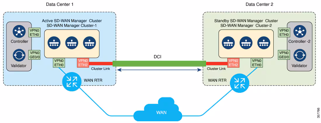
Image courtesy of
References
SD-Access
A physical network can host a variety of logical networks.
Requires hardware and software support for the fabric, plus Catalyst Center. ISE is used when identity-based policy and segmentation are part of the design.
Terms
BUM — Broadcast, Unknown Unicast, Multicast
Traffic types that aren’t great at being point-to-point.
Types
Layer 2 overlay
-
Anycast gateway enabled
- Flooding is disabled
-
No anycast gateway
- Flooding cannot be disabled
- Used if the gateway is outside the fabric
Flooding uses a multicast p2mp tunnel.
Layer 3 overlay
Stretched subnets, with Anycast gateways.
More terms
Underlay
Physical gear, configured with IPs either by hand or automatically.
The Layer 3 network VXLAN-GPO travels thru.
No VRFs, no features. Just lots of /31 links.
Typically deployed with IS-IS since it’s v4 and v6 agnostic.
This part can be automated.
VXLAN-GPO
Cisco extended the VXLAN header to include SGTs (Now called Scalable Group Tags)
VN
VN – Virtual Network
- VRF
- Anycast Gateway
- LISP Instance ID
- This is the tag field in VXLAN-GPO
Communication between VNs must go to a fusion router or a firewall.
SD access nodes
Control plane
- LISP MS/MR databases Endpoint-to-location, or EID-to-RLOC
- Each node contains the full database
- Key Lookup
- IPv4
- IPv6
- MAC Address
Fabric edge
- AKA FE
- Identifies and Auths wired endpoints
- Wireless OTT, registers v4/v6 endpoint ID
- Is the Layer 3 anycast gateway
- Can perform DHCP relay for end hosts
- Provides VN for wireless clients
- Onboards APs into the fabric, forms VXLAN tunnels with APs
- Provides the guest functionality for wireless guest
Fabric border
- Connects other L3 networks to SDA fabric
Fabric border nodes types
- Border: Known Destinations: datacenter, private cloud.
- Default Border: Unknown traffic, Internet
- Anywhere Border: Both.
The border nodes do context changes, going from one VRF to another.
Fabric intermediate
Only does IP transport
- Routing
- Multicast
Fabric edge onboarding
- (Method 1) Open Auth or MAB, user connects to a port -> host pool.
- (Method 2) 802.1x authenticates the device -> host pool.
- Host pool has a SGT, SVI and VRF instance.
- SVI is the anycast gateway (same IP address and MAC for that SVI & VRF) on all edge nodes.
- Host address is now an EID (MAC, /32 IPv4, /128 IPv6), that can be registered with the control plane node.
- Control plane signaling is LISP, dataplane is managed via VXLAN-GPO.
Fusion device
Lets devices talk between VNs.
Policy management
SGACLs, via ISE.
Site size
| Size | Endpoints | WLCs | APs | IP Pools | VNs | BNs | CPs | ENs | Notes |
|---|---|---|---|---|---|---|---|---|---|
| Fabric IAB | 1,000 | — | 50 | — | — | 1 | 1 | 1 | |
| Small | 10,000 | 2 | 500 | 100 | 32 | 2 | 2 | 100 | External WLC needed |
| Medium | 50,000 | 2 | 2,500 | 300 | 64 | 2 | 2-6 | 500 | FEW requires 2 CP nodes |
| Large | 100,000 | 2 | 10,000 | 500 | 64 | 4 | 2-6 | 1200 | 3-tier network. FEW requires 2 CP nodes |
References
Cisco Live - SD-Access Solution Fundamentals - Jerome Dolphin - BRKENS-2810
Cisco Live - SD-Access Best Practices - Ashley Burton - BRKENS-2502
Cisco Software-Defined Access Solution Design Guide
SD-Access Deployment Using Cisco Catalyst Center - Cisco
Cisco - SD-Access Wireless Design and Deployment Guide - Cisco DNA center 2.1.1
Cisco SD-Access Fabric Resources - Cisco Community
Cisco Catalyst Center
- AKA Cisco DNA Center
- Southbound (towards fabric devices)
- NETCONF, SNMP, SSH
- Northbound (towards applications)
- REST/HTTPS
Uses Security Group Tags (SGTs) for group-based segmentation and policy.
Modules
-
NCP: Network Control Platform. This module is connect via API to the GUI, and is what talks to the network gear via NETCONF, SNMP, or SSH. Does all the underlay automation.
-
NDA: Network Data Platform. Data collection and analytics. Netflow, Syslog, ERSPAN, etc.
Licensing
- Cisco Catalyst Center
- Cisco DNA Advantage
- 3, 5, and 7 year terms
License features
References
Catalyst Center 2.3.7 Data Sheet - Cisco
SD-Access LISP
- LISP
- Locater Identifier Separation Protocol
Usually an IP includes two things:
- Identity
- Location
LISP allows these to be de-coupled.
In LISP these are called namespaces.
EID
Endpoint Identifier
This is the ID portion
RLOC
Routing Locator
This is where the device is.
EID-to-RLOC
The table used to map where a identity currently is.
For wireless it could be roaming to a new AP.
VRFs
The LISP instance ID is the VRF.
References
SD-Access VXLAN
MAC-in-UDP Encapsulation.
Extends vlans to support 16 million network segments in the same administrative domain.
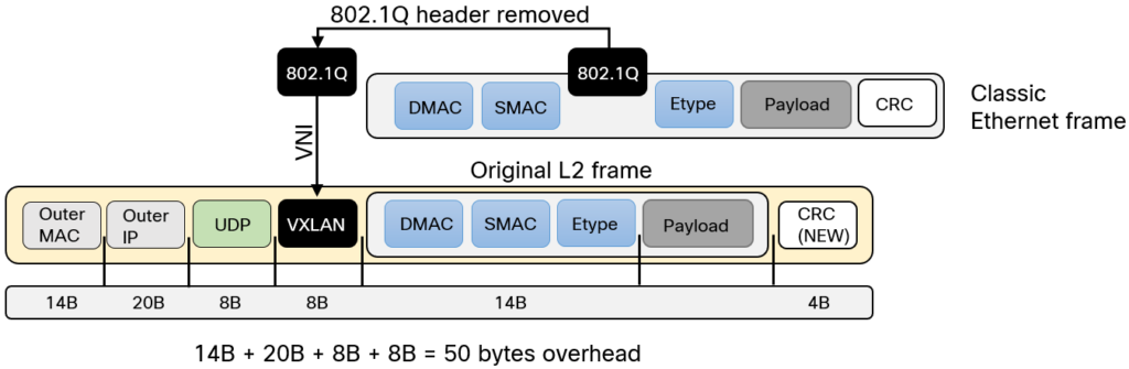
Image courtesy of Lost In Transit
VXLAN is VTEP to VTEP.
- Outer-IP-SRC, VTEP that originated the packet
- Outer-IP-DST IP, VTEP that needs the packet.
- Outer-MAC-SRC, VTEP that created the packet.
- Outer-MAC-DST, the device to reach the VTEP, the gateway.
Multi-destination Support is provided by multicast.
VNI
- Virtual Network Identifier.
- 24 bits, 16 million segments.
- Get mapped to multicast groups.
- Used for macrosegmentation.
VTEP
- Virtual Tunnel End point.
- Originates and Terminates tunnels.
- push and pop VXLAN headers.
VXLAN segment
- Only devices with the same VNI can communicate.
- AKA Overlay Network
Layer 2 overlay
- VNI is matched
- LISP Instance ID
- VLAN
Layer 3 overlay
- Endpoints are routed
- VNI is matched
- LISP Instance ID
- VRF
References
Cisco Live - SD-Access Solution Fundamentals - Jerome Dolphin - BRKENS-2810
Introduction to VXLAN – Daniels Networking Blog
Cisco Live - SD-Access Best Practices - Ashley Burton - BRKENS-2502
SD-Access VXLAN-GPO Header
Outer Ethernet Header
0 1 2 3
0 1 2 3 4 5 6 7 8 9 0 1 2 3 4 5 6 7 8 9 0 1 2 3 4 5 6 7 8 9 0 1
┌───────────────────────────────────────────────────────────────┐
│ Outer Destination MAC Address │
├───────────────────────────────┬───────────────────────────────┤
│ Outer Destination MAC Address │ Outer Source MAC Address │
├───────────────────────────────┴───────────────────────────────┤
│ Outer Source MAC Address │
├───────────────────────────────┬───────────────────────────────┤
│OptnlEthtype = C-Tag 802.1Q │ Outer.VLAN Tag Information │
├───────────────────────────────┼───────────────────────────────┘
│ Ethertype = 0x0800 │
└───────────────────────────────┘
Outer IPv4 Header
0 1 2 3
0 1 2 3 4 5 6 7 8 9 0 1 2 3 4 5 6 7 8 9 0 1 2 3 4 5 6 7 8 9 0 1
┌───────┬───────┬───────────────┬───────────────────────────────┐
│Version│ IHL │Type of Service│ Total Length │
├───────┴───────┴───────────────┼─────┬─────────────────────────┤
│ Identification │Flags│ Fragment Offset │
├───────────────┬───────────────┼─────┴─────────────────────────┤
│ Time to Live │Protocl=17(UDP)│ Header Checksum │
├───────────────┴───────────────┴───────────────────────────────┤
│ Outer Source IPv4 Address │
├───────────────────────────────────────────────────────────────┤
│ Outer Destination IPv4 Address │
└───────────────────────────────────────────────────────────────┘
Outer UDP Header
0 1 2 3
0 1 2 3 4 5 6 7 8 9 0 1 2 3 4 5 6 7 8 9 0 1 2 3 4 5 6 7 8 9 0 1
┌───────────────────────────────┬───────────────────────────────┐
│ Source Port │ Dest Port = VXLAN Port │
├───────────────────────────────┼───────────────────────────────┤
│ UDP Length │ UDP Checksum │
└───────────────────────────────┴───────────────────────────────┘
VXLAN-GPO Header
0 1 2 3
0 1 2 3 4 5 6 7 8 9 0 1 2 3 4 5 6 7 8 9 0 1 2 3 4 5 6 7 8 9 0 1
┌─┬─┬─┬─┬─┬─┬─┬─┬─┬─┬─┬─┬─┬─┬─┬─┬───────────────────────────────┐
│G│R│R│R│I│R│R│R│R│D│R│R│A│R│R│R│ Group Policy ID │
├─┴─┴─┴─┴─┴─┴─┴─┴─┴─┴─┴─┴─┴─┴─┴─┴───────────────┬───────────────┤
│ VXLAN Network Identifier (VNI) │ Reserved │
└───────────────────────────────────────────────┴───────────────┘
Inner Ethernet Header
0 1 2 3
0 1 2 3 4 5 6 7 8 9 0 1 2 3 4 5 6 7 8 9 0 1 2 3 4 5 6 7 8 9 0 1
┌───────────────────────────────────────────────────────────────┐
│ Inner Destination MAC Address │
├───────────────────────────────┬───────────────────────────────┤
│ Inner Destination MAC Address │ Inner Source MAC Address │
├───────────────────────────────┴───────────────────────────────┤
│ Inner Source MAC Address │
├───────────────────────────────┬───────────────────────────────┤
│ OptnlEthtype = C-Tag 802.1Q │ Inner.VLAN Tag Information │
└───────────────────────────────┴───────────────────────────────┘
Payload
0 1 2 3
0 1 2 3 4 5 6 7 8 9 0 1 2 3 4 5 6 7 8 9 0 1 2 3 4 5 6 7 8 9 0 1
┌───────────────────────────────┬───────────────────────────────┐
│ Ethertype of Original Payload │ │
├───────────────────────────────┘ │
│ Original Ethernet Payload │
│ │
│(Note that the original Ethernet Frame's FCS is not included) │
└───────────────────────────────────────────────────────────────┘
Frame Check Sequence
0 1 2 3
0 1 2 3 4 5 6 7 8 9 0 1 2 3 4 5 6 7 8 9 0 1 2 3 4 5 6 7 8 9 0 1
┌───────────────────────────────────────────────────────────────┐
│ New FCS (Frame Check Sequence) for Outer Ethernet Frame │
└───────────────────────────────────────────────────────────────┘
References
IETF - VXLAN Group Policy Option - draft-smith-vxlan-group-policy-05
Cisco Community - SD-Access Segmentation Design Guide
SD-Access and Wireless Integration
Control plane traffic is CAPWAP inside of VXLAN-GPO. Dataplane traffic can just ride VXLAN-GPO
Fabric design
FEW — Fabric Enabled wireless
The client mac is the EID.
SD access wireless
- CAPWAP the control plane traffic
- VXLAN-GPO the data plane, tunnel it to an edge node.
- APs act as VTEPS.
Fabric APs
- Go into the AP subnet, in the overlay
- Go in the INFRA_VN
- Use CAPWAP for control-plane only
- Converts wireless data into VXLAN-GPO, encoding the VNI, and SGT
- Join the WLC in Local mode
- 20ms of latency, max
Nonfabric design
- AKA OTT (Over The Top)
- Rides VXLAN, not VXLAN aware.
- Good for existing networks, where the wireless is already working and disruption would be costly.
CUWN wireless OTT
- CUWN: Cisco Unified Wireless Network
Everything is CAPWAP inside of VXLAN-GPO. Central switching.
FlexConnect OTT
- CAPWAP Tunnel the control traffic.
- Dump the traffic at the local switch.
Mixed mode OTT
- Some APs tunnel all their traffic back with CAPWAP.
WLC
- Subnet for the WLC goes into the underlay network, via an IGP.
IPAM integraiton
- Infoblox
- Bluecat
References
SD-Access Wireless Design and Deployment Guide - Cisco DNA center 2.1.1
Cisco SD-Access Best Practices
Ceph
Sage Weil’s 2007 PhD thesis topic at University of California, Santa Cruz.
The service Ceph provides is RADOS, Reliable Autonomic Distributed Object Store.
RADOS provides four services: LIBRADOS, RADOSGW, RBD, and CEPHFS.
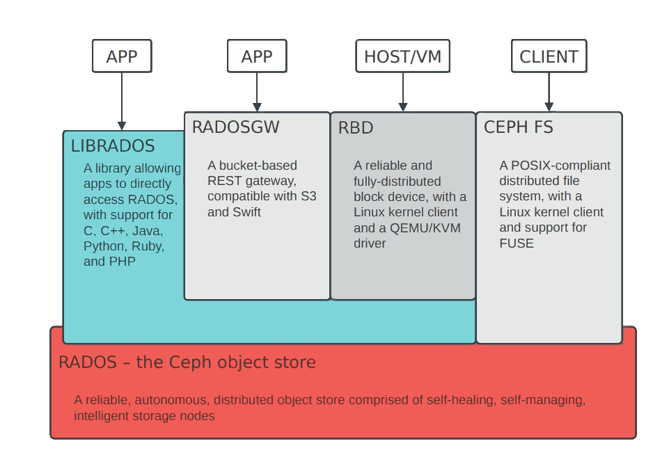
Image courtesy of Sage Weil and Lisa
OSD
OSD — Object Storage Daemon
- Manages the disks and data
- 1 per HDD or SSD
- Responsible for serving data
- Cooperatively peers, replicates, rebalances data
- 1-1000+ per cluster
MON
Mon — Monitor
- Central authority for authentication, data placement, policy
- Coordination point for all other cluster components
- 3-7 per cluster
MGR
Mgr — Manager

- Host for pluggable management functions
- Metrics
- throughput, disk usage, etc.
- 1 active, 1+ standby per cluster
MDS

- Manage file system namespace
- Store file system metadata in RADOS objects
- File and directory metadata (names, inodes)
- Coordinate file access between clients
- Manage client cache consistency, locks, leases
- Not in dataplane
- 1s - 10s active, plus standbys
RADOS cluster
References
Ceph: Reliable, Scalable, and High-Performance Distributed Storage - Sage Weil
Ceph: Managing a distributed storage system at scale - Sage Weil & Lisa - Inktank
CephFS: Architecture Introduction & New Features - Greg Farnum
Ceph Tech Talk - Intro to Ceph - 2019-JUN-27 - Sage Weil - YouTube
Ceph Tech Talk - Intro to Ceph - 2019-JUN-27 - Sage Weil - Slides
Add Cephfs to Debian
Ceph is a distributed filesystem. Here I’m adding client filesystem access to a Docker host so I can abstract away the local storage.
This will allow me to later start and stop compute loads on other nodes.
Requirements
ceph-common, the APT package- version should match the cluster
/etc/ceph/ceph.conf, how to access the cluster/etc/ceph/ceph.keyring, credentials for the cluster/mnt/docker-on-ceph, the mount point/etc/fstab, includes the the mount point
This assumes Ceph is working.
My Ceph version is 19 – that’s Squid.
I use sudo su - before all of this.
Add the repo
wget -q -O- 'https://download.ceph.com/keys/release.asc' | apt-key add -
echo deb https://download.ceph.com/debian-squid/ $(lsb_release -sc) main \
| tee /etc/apt/sources.list.d/ceph.list
Update and install
apt update && apt install ceph-common
Request permissions
On the cluster, using Ceph, request permissions for the would-be mount point.
ceph fs authorize cephfs client.grove /docker rw
Get the key
ceph auth get-or-create client.grove
Mine looks like this.
[client.grove]
key = uDEyQEqHajxXWCRU44HEhHMkvVzB2mDHoe3qfV==
caps mds = "allow rw fsname=cephfs path=/docker"
caps mon = "allow r fsname=cephfs"
caps osd = "allow rw tag cephfs data=cephfs"
Copy key to the client
It goes here.
/etc/ceph/ceph.keyring
Modify fstab
This is inside of /etc/fstab
This is TAB spaced, with six columns.
Remember to change the name= to something else.
:/docker /mnt/docker-on-ceph ceph name=orchard,_netdev,noatime 0 0
Make the mount point
mkdir /mnt/docker-on-ceph
Copy the ceph.conf file from the cluster
I do this by hand with
cat /etc/pve/ceph.conf
Mount
mount /mnt/docker-on-ceph
References
File System Guide | Red Hat Ceph Storage
Reclaim Space from Ceph for LVM
Intended when Ceph uses an entire disk for an OSD.
Useful for homelab SFF PCs running Proxmox.
Show the current setup of the block device
lsblk
ceph osd tree
Migrate data from a Ceph OSD
ceph osd out osd.1
Check if an OSD can be removed, then destroyed
while ! ceph osd safe-to-destroy osd.1 ; do sleep 10 ; done
Stop the local service – this also marks the OSD as down
systemctl stop ceph-osd@1.service
Destroy the OSD – keeps the ID reserved so it can be reused later
ceph osd destroy 1 --yes-i-really-mean-it
Remove the Ceph volume
lvremove pve/ceph
Create a Proxmox Data LVM-thin volume, size to 200G
lvcreate --size 200G --thin --name data pve
Create a Ceph volume, using the remaining space
lvcreate --extents 100%FREE --name ceph pve
Get a Ceph Key
ceph auth get client.bootstrap-osd > /var/lib/ceph/bootstrap-osd/ceph.keyring
Put Ceph onto the LV
ceph-volume lvm create --osd-id 1 --data pve/ceph
Ceph-CSI RBD
RBD — RADOS Block Device
- Virtual harddrive
- Meant for single pod dedicated writing, i.e. a database
Ceph-CSI — Container Storage Interface
Necessary to get RBDs working on K8S.
Prerequisites
These are performed on a Ceph node.
Create the RBD pool
Also enable the rbd application on it
ceph osd pool create kubernetes 128
ceph osd pool application enable kubernetes rbd
rbd pool init kubernetes
Create a client scoped to the pool
ceph auth get-or-create client.kubernetes \
mon 'profile rbd' \
osd 'profile rbd pool=kubernetes' \
mgr 'profile rbd pool=kubernetes'
Get a Ceph key for Kubernetes
ceph auth print-key client.kubernetes; echo
Install
On a machine with kubectl + the cluster kubeconfig
Install Helm
curl -fsSL https://raw.githubusercontent.com/helm/helm/main/scripts/get-helm-3 | bash
Add the chart repo
helm repo add ceph-csi https://ceph.github.io/csi-charts
helm repo update ceph-csi
Create the namespace
kubectl create namespace ceph-csi-rbd
Populate the config files
ceph-csi-rbd/values.yamlceph-csi-rbd/secret.values.yamladd to.gitignore
echo 'ceph-csi-rbd/secret.values.yaml' >> .gitignore
#
# ceph-csi-rbd/values.yaml
#
# Tell the driver how to reach the Ceph cluster (msgr v2, port 3300).
csiConfig:
- clusterID: "06184e1d-d46d-43fb-80ef-8b485942ca80"
monitors:
- "192.168.42.14:3300"
- "192.168.42.15:3300"
- "192.168.42.17:3300"
# Have the chart create the StorageClass.
storageClass:
create: true
name: csi-rbd-sc
clusterID: "06184e1d-d46d-43fb-80ef-8b485942ca80"
pool: kubernetes
imageFeatures: "layering" # safe default for kernel rbd (krbd)
provisionerSecret: csi-rbd-secret
controllerExpandSecret: csi-rbd-secret
nodeStageSecret: csi-rbd-secret
reclaimPolicy: Delete
allowVolumeExpansion: true
mountOptions: []
#
# ceph-csi-rbd/secret.values.yaml
#
# userID must NOT include the "client." prefix.
secret:
create: true
name: csi-rbd-secret
userID: kubernetes
userKey: <output of `ceph auth print-key client.kubernetes`>
(Optional) Dry-run render
helm template ceph-csi-rbd ceph-csi/ceph-csi-rbd --version 3.17.0 \
-n ceph-csi-rbd -f ceph-csi-rbd/values.yaml -f ceph-csi-rbd/secret.values.yaml
Install the chart
helm install ceph-csi-rbd ceph-csi/ceph-csi-rbd --version 3.17.0 \
--namespace ceph-csi-rbd \
-f ceph-csi-rbd/values.yaml \
-f ceph-csi-rbd/secret.values.yaml
Verify
Human Verification
# All nodeplugin (DaemonSet) + provisioner pods should be Running.
kubectl -n ceph-csi-rbd get pods
# StorageClass + Secret exist.
kubectl get sc csi-rbd-sc
kubectl -n ceph-csi-rbd get secret csi-rbd-secret
LLM Verification
This part is pure vibe-coded LLM.
End-to-end test (provisions a real RBD image, mounts it, writes/reads, cleans up):
cat <<'EOF' | kubectl apply -f -
apiVersion: v1
kind: PersistentVolumeClaim
metadata: { name: rbd-test-pvc, namespace: default }
spec:
accessModes: ["ReadWriteOnce"]
storageClassName: csi-rbd-sc
resources: { requests: { storage: 1Gi } }
---
apiVersion: v1
kind: Pod
metadata: { name: rbd-test, namespace: default }
spec:
restartPolicy: Never
containers:
- name: c
image: busybox:1.36
command: ["sh","-c","echo ceph-ok > /data/test && cat /data/test && sleep 3"]
volumeMounts: [{ name: v, mountPath: /data }]
volumes:
- name: v
persistentVolumeClaim: { claimName: rbd-test-pvc }
EOF
kubectl -n default get pvc rbd-test-pvc # -> Bound
kubectl -n default logs rbd-test # -> ceph-ok
# cleanup
kubectl -n default delete pod rbd-test
kubectl -n default delete pvc rbd-test-pvc
Using it: csi-rbd-sc is not the cluster default (local-path still is),
so request it explicitly with storageClassName: csi-rbd-sc in a PVC.
(See Ceph-CSI CephFS for making a Ceph SC the cluster default.)
Using
ceph df
rbd du -p kubernetes
Uninstall
helm uninstall ceph-csi-rbd --namespace ceph-csi-rbd
kubectl delete namespace ceph-csi-rbd
References
GitHub - ceph/ceph-csi: CSI driver for Ceph · GitHub
Ceph-CSI CephFS
CephFS — Ceph Filesystem
- Directories
- Files
- Metadata
- Shared access
Ceph-CSI — Container Storage Interface
Necessary to get CephFS working on K8S.
CephFS subvolumes live inside the existing cephfs filesystem under
/volumes/csi/<subvol>/<uuid>/
Prerequisites
These commands are performed on a Ceph node.
Create a client
ceph auth get-or-create client.k8s-cephfs mgr 'allow rw' mon 'allow r' mds 'allow rw' osd 'allow rw tag cephfs *=*'
Create the CSI subvolume group
ceph fs subvolumegroup create cephfs csi
Get a Ceph key for Kubernetes
ceph auth print-key client.k8s-cephfs; echo
Install
On a machine with kubectl + the cluster kubeconfig
Install Helm
curl -fsSL https://raw.githubusercontent.com/helm/helm/main/scripts/get-helm-3 | bash
Add the chart repo
helm repo add ceph-csi https://ceph.github.io/csi-charts
helm repo update ceph-csi
Create the namespace
kubectl create namespace ceph-csi-cephfs
Populate the config files
ceph-csi-cephfs/values.yamlceph-csi-cephfs/secret.values.yamladd to.gitignore
echo 'ceph-csi-cephfs/secret.values.yaml' >> .gitignore
#
# ceph-csi-cephfs/values.yaml
#
# ... If you see this
# libceph: mon0 (1)192.168.42.14:3300 socket closed (con state V1_BANNER)
# ceph: No mds server is up or the cluster is laggy
#
# Fix with this ...
nodeplugin:
kernelmountoptions: "ms_mode=prefer-crc"
# How the driver reaches the Ceph cluster (msgr v2, port 3300).
csiConfig:
- clusterID: "06184e1d-d46d-43fb-80ef-8b485942ca80"
monitors:
- "192.168.42.14:3300"
- "192.168.42.15:3300"
- "192.168.42.17:3300"
# Have the chart create the StorageClass (ReadWriteMany shared FS).
storageClass:
create: true
name: csi-cephfs-sc
clusterID: "06184e1d-d46d-43fb-80ef-8b485942ca80"
fsName: cephfs # the existing CephFS filesystem name
pool: "" # empty => use the filesystem's default data pool
provisionerSecret: csi-cephfs-secret
controllerExpandSecret: csi-cephfs-secret
nodeStageSecret: csi-cephfs-secret
reclaimPolicy: Delete
allowVolumeExpansion: true
#
# ceph-csi-cephfs/secret.values.yaml
#
# userID must NOT include the "client." prefix.
secret:
create: true
name: csi-cephfs-secret
userID: k8s-cephfs
userKey: <output of `ceph auth print-key client.k8s-cephfs`>
(Optional) Dry-run render
helm template ceph-csi-cephfs ceph-csi/ceph-csi-cephfs --version 3.17.0 \
-n ceph-csi-cephfs -f ceph-csi-cephfs/values.yaml -f ceph-csi-cephfs/secret.values.yaml
Install the chart
helm install ceph-csi-cephfs ceph-csi/ceph-csi-cephfs --version 3.17.0 \
--namespace ceph-csi-cephfs \
-f ceph-csi-cephfs/values.yaml \
-f ceph-csi-cephfs/secret.values.yaml
Verify
Human Verification
kubectl -n ceph-csi-cephfs get pods # nodeplugin (DaemonSet) + provisioner Running
kubectl get sc csi-cephfs-sc
LLM Verification
This part is pure vibe-coded LLM.
End-to-end ReadWriteMany test — two pods on different nodes share one volume:
cat <<'EOF' | kubectl apply -f -
apiVersion: v1
kind: PersistentVolumeClaim
metadata: { name: cephfs-rwx-test, namespace: default }
spec:
accessModes: ["ReadWriteMany"]
storageClassName: csi-cephfs-sc
resources: { requests: { storage: 1Gi } }
---
apiVersion: v1
kind: Pod
metadata: { name: cephfs-writer, namespace: default }
spec:
restartPolicy: Never
containers:
- name: c
image: busybox:1.36
command: ["sh","-c","echo hello-from-writer > /data/shared.txt; sleep 120"]
volumeMounts: [{ name: v, mountPath: /data }]
volumes:
- { name: v, persistentVolumeClaim: { claimName: cephfs-rwx-test } }
---
apiVersion: v1
kind: Pod
metadata: { name: cephfs-reader, namespace: default }
spec:
restartPolicy: Never
containers:
- name: c
image: busybox:1.36
command: ["sh","-c","for i in $(seq 1 30); do [ -f /data/shared.txt ] && cat /data/shared.txt && exit 0; sleep 2; done; exit 1"]
volumeMounts: [{ name: v, mountPath: /data }]
volumes:
- { name: v, persistentVolumeClaim: { claimName: cephfs-rwx-test } }
EOF
kubectl -n default get pvc cephfs-rwx-test # -> Bound (RWX)
kubectl -n default logs cephfs-reader # -> hello-from-writer
# cleanup
kubectl -n default delete pod cephfs-writer cephfs-reader
kubectl -n default delete pvc cephfs-rwx-test
Make it the default StorageClass
So PVCs never need storageClassName:
# demote whatever is currently default (e.g. csi-rbd-sc or local-path)
kubectl patch storageclass csi-rbd-sc \
-p '{"metadata":{"annotations":{"storageclass.kubernetes.io/is-default-class":"false"}}}'
# promote cephfs
kubectl patch storageclass csi-cephfs-sc \
-p '{"metadata":{"annotations":{"storageclass.kubernetes.io/is-default-class":"true"}}}'
Remove local-storage from K3S
Do this on all the control nodes.
root@k3s-control-tiny-2:/etc/rancher/k3s# cat config.yaml
disable:
- local-storage
Uninstall
helm uninstall ceph-csi-cephfs --namespace ceph-csi-cephfs
kubectl delete namespace ceph-csi-cephfs
# (the 'csi' subvolume group and any subvolumes remain in Ceph until removed)
References
README - ceph-csi/charts/ceph-csi-cephfs GitHub
PTP
1 second, is 1000 ms.
1 millisecond: Network latency is measured in ms, or 1 thousandth of a second 0.001.
1 microsecond
- 1 μs (a millionth) of a second
- 0.000 001
- 1000 μs is 1 ms
1 nanosecond
- 1 ns (a billionth) of a second
- 0.000 000 001
- 1000 ns is 1 μs
NTP
- An older time standard
- Can sync time between 10 to 1 ms
PTP
- Modern time standard
- Can sync time between 10 to 1 ns
- At minimum, ~1 million times more precise than NTP
PTPv1
- Defined in IEEE 1588-2002
PTPv2
- Defined in IEEE 1588-2008
- Not backwards compatible with v1
PTPv2.1
- Defined in IEEE 1588-2019
- Backward compatible with v2
1588 Clock
- Clock in the PTP time domain
- Clocks have ports
Terminating Clock
- Clock with one port
Ordinary Clock
- Clock in a terminating device
- Receives time
Boundary Clock
- Clock in a transmitting device, like an Ethernet switch
- Connects PTP domains
Transparent Clock
- Forwards PTP messages but updates the correction fields for residence time.
Grandmaster
- All clocks sync to this one clock
Master
- All clocks in a subdomain sync to the master
- The master sync’s to the grand master.
Time terms
Epoch
- The start of time
Offset
- The estimated time between a master clock sending time, and a slave clock receiving it
Uses
- Robotics, synchronizing movements
- Mobile Phone networks, telemetry, billing, logging
- Financial Networks, trade settling fairness
- Power Networks, to sync to the 60hz grid
- Science network, seismic data
Process
After PTP has time from something like a GPS device, it can pass that time along, so long as the devices in the path can mark and read timestamps.
sequenceDiagram
participant M as Master PTP Clock
participant S as Slave Device
Note over M: Create t1
M ->> S: Sync
Note over S: Record t2
M ->> S: Follow Up (t1)
Note over S: Record t1
Note over S: Create t3
S ->> M: Delay Request
Note over M: create t4
M ->> S: Delay Response (t4)
Note over S: record t4
Sync
-
Server sends Sync
- Creates t1
-
Client gets Sync
-
Creates t2
- Records t2
-
Follow up
(Nicer equipment doesn’t need to send a Follow Up, if the first Sync contains an accurate timestamp)
-
Server sends Follow-Up
- Contains t1
-
Client receives Follow-Up
- Records t1
Delay request
-
Client sends Delay-Request
- Creates t3
- Records t3
- Creates t3
-
Server receives Delay-Req
- Creates t4
Delay response
-
Server sends Delay-Response
- Contains t4
-
Client receives Delay-Response
- Records t4
Delay
Delay can only add time.
Delay is also easier, since the delay tends to be absolute.
We just need two kinds of values:
- Timestamp for message sent
- Timestamp for message received
We don’t know the offset yet, but the offset shouldn’t change much between messages.
\[\text{delay} = \frac{(t_2 - t_1) + (t_4 - t_3)}{2} \]
Offset
Offset is subtracting the client time from the server time, and also subtracting the delay.
\[\text{offset} = (t_2 - t_1) - \text{delay} \]
Config
Commands
show ptp clock
show ptp brief
show ptp parent
show ptp port
!
! Platform
!
show platform software fed switch active ptp if-id {interface-id}
Generalized PTP
!
! Using loopback0
!
ptp property P_GENERALIZED_PTP
transport unicast ipv4 local Loopback0
peer ip 198.51.100.1
exit
exit
ptp dot1as extend property P_GENERALIZED_PTP
Standard PTP
AKA IEEE 1588
Read the caveats.
ptp transport-protocol ipv4 udp
!
! four modes to choose from : two boundaries clocks
! : two transparent clocks
!
! this is the default mode, the switch doesn't participate in PTP.
!
ptp mode p2ptransparent
!
! Applying to ports
!
interface range gigabitethernet1/0/1-gigabitethernet1/0/2
ptp sync interval -3
ptp delay-req interval -3
exit
!
! Setting QoS
!
ptp ip dscp 46 message general
ptp ip dscp 46 message event
end
Resources
Cisco - Precision Time Protocol for Timing in IP Fabric for Media Guide
Cisco - Technote - Troubleshoot Precision Time Protocol on the Catalyst 9000
Cisco - Whitepaper - PTP and SyncE basics with Cisco IOS XR Configuration
Riedel - Transparent versus Boundary Clocks (PTP) in Broadcast Environments
SyncE
SyncE synchronizes clock frequency over an Ethernet port.
It does not synchronize time-of-day, that’s done by PTP, IEEE 1588.
Setting as oscillator to a frequency is syntonization.
References
-
ITU-T Rec. G.8261 - Architecture and the wander performance of SyncE networks
-
ITU-T Rec. G.8262 - Synchronous Ethernet clocks for SyncE
-
ITU-T Rec. G.8264 - Ethernet Synchronization Messaging Channel (ESMC)
Config options
ITU-T G.813 option 1 clock (QL-SEC)
EEC-option 1
ITU-T G.812 type IV clock (QL-ST3)
EEC-option 2
Terms
Synchronous Ethernet and IEEE 1588 in Telecoms
-
Time Interval: Distance between two events, (measured in seconds), milliseconds, microseconds, nanoseconds, picoseconds
-
Frequency: Rate of a repetitive event. Measured in cycles per second. A device that produces frequency is an oscillator.
-
T0: System Clock (line interface output)
-
T1: Timing Reference signal derived from STM-N (STS-N/SyncE) input.
-
T2: Timing Reference signal derived from 2048/1544 kbit input (input from PDH)
-
T3: Timing reference signal derived from 1544 or 2048 with SSM.
-
T4: Clock-interface output.
-
OSC: Internal ST3 oscillator
-
SSM: Synchronization Status Message
-
ESMC: Ethernet Synchronization Message Channel
-
MTIE: Maximum time interval error is a measure of the worst case phase variation of a signal with respect to a perfect signal over a given period of time.
-
TDEV: Time deviation is a statistical analysis of the phase stability of a signal over a given period of time.
Wireless
show chassis detail
show chassis rmi
Lightweight modes
Terms
WECA — Wireless Ethernet Compatibility Alliance
- Now called the Wi-Fi Alliance
MAP — Mesh Access Point
Client-Serving AP modes
Local
- Default
- Tunnels traffic with CAPWAP
- Must be connected to the WLC to work
- No mesh
FlexConnect
- CAPWAP or AP LAN port
- No mesh
Bridge
Two submodes:
-
Bridge-root
-
Has wired access, provides mesh access
Bridge-mesh
- Relies on other APs for CAPWAP backhaul
Network management AP modes
Monitor
- Dedicated Monitoring
- RRM and Rogues
Rogue Detector
- Turn off RF
- Monitor the LAN for on-wire rogues
- Deprecated
Sniffer
- Capture all Wi-Fi traffic on 1 channel
- Tunneled in CAPWAP to WLC
- forwarded to a machine running OmniPeek or Wireshark
SE-Connect
- Spectrum Expert
- Clean Air
References
Cisco Live - The Great Wi-Fi Architecture Debate - Simone Arena
Cisco Wireless Controller Configuration Guide, Release 8.10
Wireless Channels
2ghz
1, 6, and 11 are the recommended channels in the US. There is a lot of overlap on 2ghz.

5ghz
The Wi-Fi Alliance helped drive use of the 5 GHz band for Wi-Fi.
UNII — Unlicensed National Information Infrastructure
TDWR – Terminal Doppler Weather Radio
- Uses and relies on a 5ghz signal to detect weather events
DFS — Dynamic Frequency Selection
- Weather radar is the primary user of DFS frequencies
- WLAN equipment must not transmit if it senses TDWR

6ghz

Graphics
Graphics on this page are rendered with python and matplotlib from ariadne-notes/wifi-charts.
References
Channel numbers, center frequencies, and channel widths are from IEEE Std 802.11-2024. United States regulatory allocation and operating constraints are from FCC rules.
FCC - 5GHz Unlicensed Spectrum
FCC 47 CFR 15.247 - Operation within the bands 902-928 MHz, 2400-2483.5 MHz, and 5725-5850 MHz
FCC 47 CFR 15.407 - General technical requirements for U-NII devices
Unlicensed National Information Infrastructure - Wikipedia
NTIA Report 20-544 - Lessons Learned from the Development and Deployment of 5 GHz …
Cisco Wireless Security
WPA – Wireless Protected Access
WPA, includes TKIP
WPA2, includes AES
WPA3, removes older standards like TKIP
Authentication, abstracted
Courtesy of BRKEWN-3004.
sequenceDiagram
participant S as Supplicant<br/>Phone, PC, Laptop, Etc.
participant A as Authenticator<br/>(WLC)
participant AS as Authentication Server<br/>(ISE)
A->>S: Association Response
A->>S: Identity Request
S->>A: Identity Response
A->>AS: Identity Response
S<<->>AS: EAP Type Negotiation
S<<->>AS: Authentication Sequence
AS->>A: EAP Success
A->>S: EAP Success
Encryption, abstracted
Courtesy of BRKEWN-3004.
PTK — Pairwise Transient Key
GTK — Group Transient Key
PMK — Pairwise Master Key
STA — Station
Anonce – Authenticator nonce, a random value generated by the authenticator
Snonce — Supplicant nonce, a random value generated by the supplicant
\(PTK = SHA(PMK + ANonce + SNonce + AP MAC + STA MAC)\)
sequenceDiagram
participant S as Supplicant
participant A as Authenticator<br/>(WLC)
participant AS as Authentication Server<br/>(ISE)
Note over AS: PMK
AS->>A: EAP Success (PMK)
A->>S: EAP Success
Note over S: PMK
rect rgb(235, 245, 235)
Note over S,A: Four-Way Handshake
A->>S: ANonce
S->>A: SNonce, MIC
Note over S,A: PTK, GTK derived
A->>S: ANonce, MIC, GTK, Sequence #
S->>A: ACK
end
References
Cisco Live - Understanding Wireless Security - Mark Krischer - BRKEWN-3004
OFDM
OFDM — Orthogonal frequency domain multiplexing
- Multiple carriers for one datastream
- Subcarriers are orthogonal
- There is a guard interval
The orthogonality requires that the subcarrier spacing is:
\( \Delta f = \frac{k}{T_U} \) Hz, where
\( k \) is a positive integer, typically equal to 1
\( T_U \) seconds, the useful symbol duration (the receiver-side window size)
This stipulates that each carrier frequency undergoes \( k \) more complete cycles per symbol period than the previous carrier.
Therefore, with \( N \) subcarriers, the total passband bandwidth will be \( B \approx N \cdot \Delta f \) (Hz).
Courtesy of Wikipedia.
What does this look like?
If \( \Delta f \) Hz is chosen correctly, transmitted signals look like this…
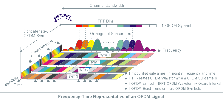
Image courtesy of Keysight.
- 8 subcarriers
- 1 OFDM symbol per unit interval
- Orthogonal signals eliminate crosstalk between subcarriers
Terms
- A waveform in the communication channel that persists for a period of time
Symbol Duration Time
- AKA, unit interval
- AKA, baud rate
\( T_s = \frac{1}{f_s} \)
FFT — Fast Fourier Transform
- Used to decode a recovered RF signal
IFFT — Inverse Fast Fourier Transform
- Used to encode a symbol into RF
References
Concepts of Orthogonal Frequency Division Multiplexing (OFDM) and 802.11 WLAN
Orthogonal frequency-division multiplexing - Wikipedia
OpenConfig Automation
- Consortium of network operators
- Not a Standards Org
- Wants good FOSS YANG models
- Wants good FOSS to interact with YANG models
OpenConfig is a collaborative effort by network operators to develop programmatic interfaces and tools for managing networks in a more dynamic, vendor-neutral way.
Source: What is Openconfig?
Ecosystem
Google has done a lot of work in this area, their contributions are FOSS, and they’d like to see it widely adopted.
Most of the existing network paradigms fail at scale.
SNMP at scale is very broken.
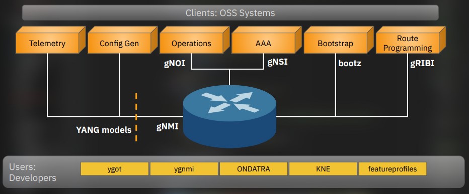
Courtesy of NANOG 90, Rob Shakir’s Keynote
References
google/gnxi: gNXI Tools - GitHub
Rob Shakir’s - Tag “openconfig”
Rob Shakir’s - Public Projects
Network Visibility for the Automation Age - Rob Shakir
IETF 98 - Observations on Modeling Configuration and State in YANG
RFC 5218: What Makes for a Successful Protocol? | RFC Editor
gRPC
gRPC — gRPC Remote Procedure Call
gRPC allows writing network level apps using data in different places.
It’s a modern connection oriented, datastream.
Terms
BiDi — Bidirectional
Uses HTTP/2
- Multiplexing
- Header Compression
- Binary Framing
- Firewalls and proxies understand HTTP/2
Services
- Client - Server Oriented
- Streaming
- Blocking and non-blocking
- Flow control
- Protocol Buffers
- Message exchange
- gRPC clients talk to gRPC servers
- Uses HTTP/2 as transport
- Does not expose HTTP2 to the user
- Easily encrypted with TLS
- Persistent connections
- Heartbeats
- Uses application-level queue coalescence
Message Types
Programs can do remote function calls on other servers.
flowchart LR
%%{init: {'flowchart': {'curve': 'monotoneX'}}}%%
subgraph cpp["C++ Service"]
stub3["gRPC\nStub"]
end
subgraph ruby["Ruby Client"]
stub1["gRPC\nStub"]
end
subgraph android["Android-Java Client"]
stub2["gRPC\nStub"]
end
stub2 -->|"Proto Request"| cpp
cpp -->|"Proto Response(s)"| stub2
stub1 -->|"Proto Request"| cpp
cpp -->|"Proto Response(s)"| stub1
Transaction Types
Unary
- One request
- One response
Client Streaming
- Client sends multiple messages
- Server sends one response
Server Streaming
- Client sends one request
- Server sends multiple messages
Bidirectional Streaming
- Two independent streams
- Any read or write order
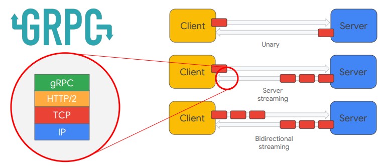
Image courtesy of Rob Shakir.
gRPC network applications
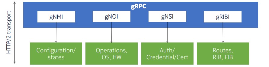
Image courtesy of Reda Laichi - NANOG 93.
Protocol buffers
This defines the data structure to send.
-
Small local records
-
Messages
-
end in
.proto
message Person {
string name = 1;
int32 id = 2;
bool has_ponycopter = 3;
}
… Gets fed into the protocol buffer compiler protoc
Allows name(), set_name()
Now the Person class can serialize and retrieve protocol buffer messages.
References
gRPC - Motivation and Design Principles
gRPC - Core concepts, architecture and lifecycle
KubeCon 2018 - gRPC Introduction - Jayanth Kolhe
NANOG 93 - gRPC Services under one roof - Reda Laichi - Nokia
Network Visibility for the Automation Age - Rob Shakir
gNMI
gNMI — gRPC Network Management Interface
Intended to obsolete SNMP.
- get
- set
- subscribe
- collect
Setting an IPv4 address
This is done in gNMI via gRPC and a YANG model.
/interfaces/interface[name=g0/0/0/0]/subinterfaces/subinterface[index=0]/ipv4/addresses/address[ip=10.0.0.1]/config/
- ip: 10.0.0.1
- prefix-length: 24
References
Cisco - Programmability Configuration Guide, IOS XE 17.13.x - gNMI Protocol
Cisco Live - gRPC, gNMI, gNOI… Oh My! - Jeremy Cohoe - BKDEV-2017
OpenConfig - gNMI specification
gNOI
gNOI — gRPC Network Operations Interface
Intended for operational use and ran as a client to connect to gNMI equipment.
Functions
SYSTEM
- Ping
- Traceroute
- Time
- SetPackage
- SwitchControlProcessor
- Reboot
- RebootStatus
- CancelReboot
- KillProcess
FILE
- Get
- TransferToRemote
- Put
- Stat
- Remove
FACTORYRESET
- Start
HEALTHZ
- Get
- List
- Acknowledge
- Artifact
- Check
OS
- Install
- Activate
- Verify
LINKQUALIFICATION
- Create
- Get
- Capabilities
- Delete
- List
Clients
References
NANOG 93 - gRPC Services under one roof - Reda Laichi - Nokia
gNSI
gNSI – gRPC Network Security Interface
Functions
Certz
- Certificate Management
- CRL management
Acctz
- Accounting records
Pathz
- Access control for gNMI paths
Authz
- Authorization for users to access gRPC services
References
NANOG 93 - gRPC Services under one roof - Reda Laichi - Nokia
gRIBI
gRIBI — gRPC Routing Information Base Interface
Routers do a poor job of providing telemetry for “I have the route installed.”
- injected entries are interdependent (rely on other routes being present)
- Request/response driven
- Separate from other protocols
- A normal vendor neutral interface
- Treated as control plane
- As if learned via a dynamic protocol
- Not config
Functions
- Route Injection
Client
References
NANOG 93 - gRPC Services under one roof - Reda Laichi - Nokia
GitHub - openconfig/gribi: A gRPC Interface to a Network Element RIB
gNxI
gNxI — gRPC Network X Interface
Usually combines the gNMI and gNOI tools.
Unsecure Setup
Config
gnxi
gnxi server
gnxi port <port number>
Verify
show gnxi state
References
gNMI Protocol - IOS-XE - Cisco
IETF Automation
IAB1 organized a workshop between June 4 to June 6th in 2002 to establish a dialog between network operators and developers to guide the IETF on network automation.
That workshop is recorded in RFC 3535.
YANG, RESTCONF, NETCONF, and gRPC try to solve these problems.
- Operator Requirements
During the breakout session, the operators were asked to identify needs that have not been sufficiently addressed. The results produced during the breakout session were later discussed and resulted in the following list of operator requirements.
- Ease of use is a key requirement for any network management technology from the operators point of view.
- It is necessary to make a clear distinction between configuration data, data that describes operational state and statistics. Some devices make it very hard to determine which parameters were administratively configured and which were obtained via other mechanisms such as routing protocols.
- It is required to be able to fetch separately configuration data, operational state data, and statistics from devices, and to be able to compare these between devices.
- It is necessary to enable operators to concentrate on the configuration of the network as a whole rather than individual devices.
- Support for configuration transactions across a number of devices would significantly simplify network configuration management.
- Given configuration A and configuration B, it should be possible to generate the operations necessary to get from A to B with minimal state changes and effects on network and systems. It is important to minimize the impact caused by configuration changes.
A mechanism to dump and restore configurations is a primitive operation needed by operators. Standards for pulling and pushing configurations from/to devices are desirable.
It must be easy to do consistency checks of configurations over time and between the ends of a link in order to determine the changes between two configurations and whether those configurations are consistent.
- Network wide configurations are typically stored in central master databases and transformed into formats that can be pushed to devices, either by generating sequences of CLI commands or complete configuration files that are pushed to devices. There is no common database schema for network configuration, although the models used by various operators are probably very similar. It is desirable to extract, document, and standardize the common parts of these network wide configuration database schemas.
- It is highly desirable that text processing tools such as diff, and version management tools such as RCS or CVS, can be used to process configurations, which implies that devices should not arbitrarily reorder data such as access control lists.
- The granularity of access control needed on management interfaces needs to match operational needs. Typical requirements are a role-based access control model and the principle of least privilege, where a user can be given only the minimum access necessary to perform a required task.
- It must be possible to do consistency checks of access control lists across devices.
- It is important to distinguish between the distribution of configurations and the activation of a certain configuration. Devices should be able to hold multiple configurations.
- SNMP access control is data-oriented, while CLI access control is usually command (task) oriented. Depending on the management function, sometimes data-oriented or task-oriented access control makes more sense. As such, it is a requirement to support both data-oriented and task-oriented access control.
References
RFC 3535: Overview of the 2002 IAB Network Management Workshop | RFC Editor
-
Internet Architecture Board ↩
YANG
YANG is a Data Modeling Language
Data Modeled
- Config
- State
- RPCs (to make changes)
- Notifications (to get events)
YANG was intended for NETCONF.
- Functional Overview
YANG is a language used to model data for the NETCONF protocol. A YANG module defines a hierarchy of data that can be used for NETCONF- based operations, including configuration, state data, Remote Procedure Calls (RPCs), and notifications. This allows a complete description of all data sent between a NETCONF client and server.
Source RFC 6020 Section 4.1.
Terms
YANG — Yet Another Next Generation
Structured
- Data that is formated for automation to use
- Data that follows a schema
Schema
- Rules around how data is allowed to be structured
Why
Device CLI output provides unstructured data
%LINEPROTO-5-UPDOWN: Line protocol on Interface GigabitEthernet0/9, changed state to down
YANG provides structured data which follows a schema
<config xmlns="http://tail-f.com/ns/config/1.0">
<router xmlns="http://com/example/routermodel">
<name>switch</name>
<address>192.168.0.10</address>
<operational-status>down</operational-status>
<interface>
<type>GigabitEthernet</type>
<enabled>true</enabled>
<interface-id>0/9</interface-id>
</interface>
</router>
</config>
Features
- Tree structured
- Defined structured
- Modular
- Encoding Variety
- XML, JSON
- Meant for automated tooling
Node Types
Container
- Groups nodes
Leaf
- A data
Leaf-List
- Multiple units of one data
List
Models
Different organizations make different models.
At present multiple models are needed to get all features.
This is a BGP example.
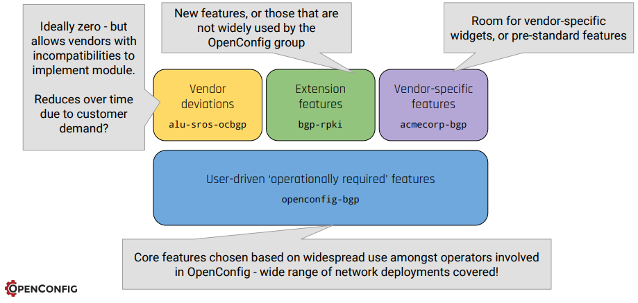
Courtesy of IETF 98, Rob Shakir & Anees Shaikh
- AKA, Vendor Model
- AKA, Native Model
- AKA, IOS-XE Model
- Best Supported
- Industry supported
- Primary focus: operational usability
- Secondary focus: ease to implement
- Very New
- Associated with the Linux Foundation
References
Cisco Blog - Native, IETF, OpenConfig… Why so many YANG models? - Hank Preston
Cisco Live - Exploring YANG Data Modeling - Aayushi Mahajan - DEVNET-1882
GitHub - OpenConfig YANG models
IETF 98 - Observations on Modeling Configuration and State in YANG
RFC 6020 - YANG - A Data Modeling Language for the Network Configuration Protocol (NETCONF)
RESTCONF
RESTCONF uses HTTP to send command operations to network equipment.
The data is encoded with XML or JSON.
Config
conf t
aaa new-model
aaa authentication login default local
aaa authorization exec default local
username admin privilege 15 secret cisco123
!
! This is a web service, turn on http
!
ip http secure-server
restconf
Validate
RESTCONF relies on DMI and nginx
restconf-router# show platform software yang-management process
confd : Running
nesd : Running
syncfd : Running
ncsshd : Running
dmiauthd : Running
nginx : Running
ndbmand : Running
pubd : Running
Get an IP address
This is done from the linux commandline via curl
--insecure is added because Cisco generates its own self-signed certificates.
ariadne@tesseract:~$ curl --insecure --user admin:cisco123 \
-H "Accept: application/yang-data+json" \
https://192.168.52.199/restconf/data/Cisco-IOS-XE-native:native/interface/Loopback=0
{
"Cisco-IOS-XE-native:Loopback": {
"name": 0,
"ip": {
"address": {
"primary": {
"address": "1.1.1.1",
"mask": "255.255.255.255"
}
}
}
}
}
Set an IP address
More command line, just with a PATCH message.
ariadne@tesseract:~$ curl --insecure --user admin:cisco123 \
-X PATCH \
-H "Accept: application/yang-data+json" \
-H "Content-Type: application/yang-data+json" \
https://192.168.52.199/restconf/data/Cisco-IOS-XE-native:native/interface/Loopback=0 \
-d '{
"Cisco-IOS-XE-native:Loopback": {
"name": 0,
"ip": {
"address": {
"primary": {
"address": "2.2.2.2",
"mask": "255.255.255.255"
}
}
}
}
}'
Reference
Programmability Configuration Guide, Cisco IOS XE 17.17.x
NETCONF
Config
conf t
aaa new-model
aaa authentication login default local
aaa authorization exec default local
username admin privilege 15 secret cisco123
!
! This service relies on SSH
!
netconf-yang
Validate
restconf-router#show netconf-yang status
netconf-yang: enabled
netconf-yang ssh port: 830
netconf-yang candidate-datastore: disabled
Setting an IP address
I performed this lab inside a linux virtual environment.
- Load a python virtual environment
python3 -m venv ~/netconf-lab
- Activate it
source ~/netconf-lab/bin/activate
- Install ncclient
pip install ncclient
- Enter the python shell
python
- Connect to device:
>>> conn = manager.connect(
host="192.168.52.199",
port=830,
username="admin",
password="cisco123",
hostkey_verify=False,
device_params={"name": "iosxe"}
)
- Paste in a payload, follow the XML
>>> payload = """
<config>
<native xmlns="http://cisco.com/ns/yang/Cisco-IOS-XE-native">
<interface>
<Loopback>
<name>5</name>
<ip>
<address>
<primary>
<address>5.5.5.5</address>
<mask>255.255.255.255</mask>
</primary>
</address>
</ip>
</Loopback>
</interface>
</native>
</config>
"""
>>> conn.edit_config(target="running", config=payload)
<?xml version="1.0" encoding="UTF-8"?>
<rpc-reply xmlns="urn:ietf:params:xml:ns:netconf:base:1.0" message-id="urn:uuid:5edcd8ca-3e51-4581-8bce-87f7eb939735" xmlns:nc="urn:ietf:params:xml:ns:netconf:base:1.0"><ok/></rpc-reply>
Reference
Programmability Configuration Guide, Cisco IOS XE 17.17.x
RFC 3535, 20 Years Later
IAB organized a workshop between June 4 to June 6th in 2002 to establish a dialog between network operators and developers to guide the IETF on network automation.
That workshop is recorded in RFC 3535.
Twenty years later, how is progress?
| RFC3535 Requests | Solved? |
|---|---|
| EASE-USE | Config yes, monitor no |
| CONFIG-OPS-SEPARATE | Yes |
| CONFIG-OPS-FETCH-SEPARATE | Yes |
| NETWORK-NOT-DEVICE | Mostly |
| NETWORK-WIDE-TRANSACTIONS | Yes |
| CONFIG-DIFF | Yes |
| CONFIG-DUMP-RESTORE | Yes |
| CONFIG-CONSISTENCY-CHECK | Implementation-specific |
| CONFIG-NETWORK-WIDE-SCHEMA | Yes |
| TXT-PROCESSING-TOOLS | Deployment-specific |
| ACCESS-CONTROL-OPS-CENTRIC | Implementation-specific |
| ACCESS-CONTROL-CHECKS | Implementation-specific |
| CONFIG-SEPARATE-DISTRIB-ACTIV | Yes |
| ACCESS-CONTROL-BOTH-DATA-TASK | Yes |
Ongoing Industry Problems
Models tend to be proprietary since the vendors consider technology their competitive advantage.
Operators don’t want to share how they use their models, since … being good at networking is their competitive advantage.
The industry wants XaaS – X as a Service, but to get there, data models are required to specify everything.
No data models, no network API.
IETF is slow
IS-IS for SR was published in 2019, the YANG model took 5 years to come out.
References
MDT
Terms
ST — Streaming Telemetry
MDT — Model Driven Telemetry
- Can be ordinary TCP
- Can also use gRPC, to add TLS
TCP dial-in
- Collector establishes a connection
- Then subscribes
sequenceDiagram
participant C as Collector
participant R as Router
C->>R: SYN
R->>C: SYN-ACK
C->>R: ACK
R->>C: Telemetry data
TCP dial-out
- Telemetry is pushed to the collector
- As soon as it changes (low latency)
- When in changes (low throughput)
sequenceDiagram
participant C as Collector
participant R as Router
R->>C: SYN
C->>R: SYN-ACK
R->>C: ACK
R->>C: Telemetry data
References
Cisco - Whitepaper - Model Driven Telemetry
Cisco Live - gRPC, gNMI, gNOI … Oh My! - Jeremy Cohoe - BRKDEV-2017
NANOG73 - SNMP is Dead - Carl Lebsack, Rob Shakir
XRdocs - Model-Driven Telemetry: Dial-In or Dial-Out ? | Telemetry
Cisco IQ
Launched: Nov 4th, 2025
General Availability: April 29, 2026
A web dashboard meant to help with the Cisco CX experience, harnessing a combination of Agentic AI, and customer provided Telemetry.
The Basic Tier works with just the cloud dashboard iq.cisco.com
Standard and Signature use the same dashboard, enhanced with Telemetry from Cisco IQ Link, the On-Prem data collector.
Cisco IQ can make a variety of data-driven network recommendations.
From the News Release.
Over 40 percent of outages start as misconfigurations nobody caught in time.
Sophisticated actors do not need a novel exploit.
They are going after aged infrastructure organizations knew about and did not prioritize.
Our Talos team confirmed it: 40% of top-targeted vulnerabilities last year impacted end-of-life devices.
32% are over a decade old.
Liz Centoni - Executive Vice President, Chief Customer Experience Officer, Cisco
Terms
CX — Customer Experience.
Cisco’s name for their customer support organization.
EOL — End of Life
A process that guides the final business operations associated with the Cisco Product life cycle.
The end-of-life process consists of a series of technical and business milestones and activities that, once completed, make a Product obsolete.
Once obsolete, the Product is not sold, improved, maintained, or supported.
LDoS — Last Day of Support
The last date to receive support as entitled by active service contracts for covered Cisco hardware and software. After this date, support is no longer available.
Support tiers
These are tied to service contract levels.
Basic
- CX Case Management
- Self-Service Troubleshooting
- Asset Inventory
- Reports
- EOL
- Support
- Security Advisories
- Field Notices
- Dashboard
- LDoS
Standard
- Requires Cisco IQ Link Deployment
- Insights into previous tier
- New Insights
- Security Hardening Insights
- Configuration Insights
- CX Case Insights
Signature
- Config Recommendations
- Security Hardening Recommendations
Features
Feature availability is tied to the support level: Basic, Standard, or Signature
Assets application
- Overview
- Device Discovery
- Criticality Insights
- Inventory
- Hardware (HBOM)
- Software (SBOM)
- Crypto (CBOM)
- Asset Tags
- Service Contracts
- End-of-Life
Assessments overview
- Findings by Asset
- Security Advisories
- Security Hardening
- Configuration
- Field Notices
Support application
- Overview
- Cases
- RMAs
AI assistant
- Security Hardening compared to CISA hardening guidelines
- Configuration evaluation against best practices
- Troubleshooting
- CX Case Handling
- Escalate an open case
- Raise Severity
- Request a new engineer
- Re-queue the case
Deployment models
SaaS
Hosted in the cloud, part of the support contract.
Comes with an optional collector called Cisco IQ Link
- Deployed VM
- One Telemetry source is SNMP
- Includes a RADKit deployment
- Uses the cloud LLM for inference
- Does not train the AI
- Cisco’s AI Transparency Technical Note
- Cisco’s Offer Disclosure
- Does not train the AI
On-Prem Tethered
- Connected to the cloud for software updates
- Cisco IQ Virtual Appliance
- Unreleased, Expected FY27
- On device LLM
Air Gapped
Same as above, but no automatic updates, and no external connections.
Cisco Live AI integration examples
Peer Benchmarking
How does my network compare to similar networks in my business vertical?
Device Migration
- Box A to B
Network OS Migration
- IOS-XE to IOS-XR
Network Architecture Migration
- IPv4 to IPv6
- Classical Networking to Controller Based
- MPLS to SRv6
References
Cisco Live - Cisco IQ Your AI Superpower - Youtube
Cisco Newsroom - Cisco launches Cisco IQ, …
Cisco IQ Documentation - Cisco
Cisco IQ Frequently Asked Questions
Cisco Newsroom - Cisco IQ General Availability
Products - End-of-Life Policy - Cisco
Cisco IQ Link
- AKA, The Collector.
Necessary for the Standard and Signature tier.
Telemetry examples:
- SNMP
- Software Versions
- Crypto being used for VPNs
Can also use Data Connectors to talk to other Managers, like On-Prem SD-WAN Manager, or On-Prem Catalyst Center.
VM requirements
This set of requirements is for 10K devices:
- 16 vCPU
- 28GB RAM
- 600 GB
- Thick Provision
- Disk write speed must be greater than 70 megabytes per second
IPv4 and DNS requirements
- a v4 address
- DNS A Record (for the VM)
- DNS PTR Record (for the IP the VM is using)
External network connectivity requirements
These must work and be reachable in DNS.
US Market
- us-west-2.iq.cisco.com
- ng.acs.agent.us.csco.cloud
EMEA Market
- eu-central-1.iq.cisco.com
- ng.acs.agent.emea.csco.cloud
APJC Market
- ap-southeast-2.iq.cisco.com
- ng.acs.agent.apjc.csco.cloud
Port requirements
| Port | Protocol | Purpose |
|---|---|---|
| 22 | TCP | Admin CLI and Cisco Support |
| 443 | TCP | Cisco IQ Link UI and API |
| 53 | UDP/TCP | DNS |
| 123 | UDP | NTP |
| 161 | UDP | SNMP |
Supported hypervisors
- VMware ESXi
- Microsoft Hyper-V Server
- Red Hat KVM
Internal network requirements
The internal network needs at least v4 /20, 4096 IPv4 addresses.
OK candidates are:
10.255.240.0/20192.168.240.0/20172.31.240.0/20
This cannot overlap with anything Cisco IQ Link needs to reach on the managed network.
Data connectors
- Intersight
- Meraki Dashboard
- On-Prem SD-WAN Manager
- On-Prem Catalyst Center
References
Cisco IQ Link Getting Started Guide v1.1.0 - Cisco
Ansible Basics
Basic Ansible
This was done on a home lab running Debian 11. tesseract is my control-node.
- Add Ansible to Sources list
- Update the OS Sources
- Install Ansible
- Create SSH keys
- Tell Ansible to use
ssh-agentso you don’t have to retype passwords - Use Ansible to copy the controle node SSH key to the ansible hosts
- Use an Ansible playbook to ping the devices
- Use an Ansible playbook to upgrade the devices
Add Ansible to sources list
echo "deb http://ppa.launchpad.net/ansible/ansible/ubuntu focal main" | sudo tee /etc/apt/sources.list.d/ansible.list
sudo apt-key adv --keyserver keyserver.ubuntu.com --recv-keys 93C4A3FD7BB9C367
sudo apt update
Install Ansible
sudo apt install ansible
Define hosts, create host file
Do not put special characters (like -) into the group names. Hosts should be FQDNs.
ariadne@tesseract:~/ansible$ cat /etc/ansible/hosts
[proxmox]
<hosts redacted>
[docker]
<hosts redacted>
[k8s]
<hosts redacted>
[linux]
<hosts redacted>
Define defaults, modify ansible.cfg
ariadne@tesseract:/etc/ansible$ cat ansible.cfg
[output omitted]
[defaults]
host_key_checking = False
remote_user = ariadne
Create A public SSH key to allow passwordless access
I’m using an internal linux host called tesseract. It doesn’t use a password, it’s a home lab.
ariadne@tesseract:~$ ssh-keygen -t rsa -b 4096 -C "ariadne@tesseract.haske.org"
Write A playbook to copy the SSH keys
ariadne@tesseract:~/ansible$ cat copy_ssh_keys_test.yml
---
- name: Copy SSH key to hosts
hosts: all
become: yes
tasks:
- name: Set authorized key taken from file
authorized_key:
user: ariadne
state: present
key: "{{ lookup(file, /home/ariadne/.ssh/id_rsa.pub) }}"
Run it
ariadne@tesseract:~/ansible$ ansible-playbook -k copy_ssh_keys.yml
SSH password:
PLAY [Copy SSH key to hosts] ***********************************************************************************************************************************************************************************************************************************
TASK [Gathering Facts] *****************************************************************************************************************************************************************************************************************************************
ok: [hosts-redacted]
ok: [hosts-redacted]
ok: [hosts-redacted]
ok: [hosts-redacted]
ok: [hosts-redacted]
ok: [hosts-redacted]
ok: [hosts-redacted]
ok: [hosts-redacted]
ok: [hosts-redacted]
ok: [hosts-redacted]
ok: [hosts-redacted]
ok: [hosts-redacted]
ok: [hosts-redacted]
ok: [hosts-redacted]
ok: [hosts-redacted]
TASK [Set authorized key taken from file] **********************************************************************************************************************************************************************************************************************
ok: [hosts-redacted]
ok: [hosts-redacted]
ok: [hosts-redacted]
ok: [hosts-redacted]
ok: [hosts-redacted]
ok: [hosts-redacted]
ok: [hosts-redacted]
changed: [hosts-redacted]
changed: [hosts-redacted]
changed: [hosts-redacted]
changed: [hosts-redacted]
changed: [hosts-redacted]
changed: [hosts-redacted]
changed: [hosts-redacted]
changed: [hosts-redacted]
PLAY RECAP *****************************************************************************************************************************************************************************************************************************************************
hosts.redacted : ok=2 changed=0 unreachable=0 failed=0 skipped=0 rescued=0 ignored=0
hosts.redacted : ok=2 changed=0 unreachable=0 failed=0 skipped=0 rescued=0 ignored=0
hosts.redacted : ok=2 changed=1 unreachable=0 failed=0 skipped=0 rescued=0 ignored=0
hosts.redacted : ok=2 changed=1 unreachable=0 failed=0 skipped=0 rescued=0 ignored=0
hosts.redacted : ok=2 changed=1 unreachable=0 failed=0 skipped=0 rescued=0 ignored=0
hosts.redacted : ok=2 changed=1 unreachable=0 failed=0 skipped=0 rescued=0 ignored=0
hosts.redacted : ok=2 changed=1 unreachable=0 failed=0 skipped=0 rescued=0 ignored=0
hosts.redacted : ok=2 changed=1 unreachable=0 failed=0 skipped=0 rescued=0 ignored=0
hosts.redacted : ok=2 changed=1 unreachable=0 failed=0 skipped=0 rescued=0 ignored=0
hosts.redacted : ok=2 changed=1 unreachable=0 failed=0 skipped=0 rescued=0 ignored=0
hosts.redacted : ok=2 changed=0 unreachable=0 failed=0 skipped=0 rescued=0 ignored=0
hosts.redacted : ok=2 changed=0 unreachable=0 failed=0 skipped=0 rescued=0 ignored=0
hosts.redacted : ok=2 changed=0 unreachable=0 failed=0 skipped=0 rescued=0 ignored=0
hosts.redacted : ok=2 changed=0 unreachable=0 failed=0 skipped=0 rescued=0 ignored=0
hosts.redacted : ok=2 changed=0 unreachable=0 failed=0 skipped=0 rescued=0 ignored=0
Write a playbook to upgrade everything
ariadne@tesseract:~/ansible$ cat upgrade-everything.yml
---
- name: Update and upgrade apt packages
hosts: all
become: true
tasks:
- name: Update apt cache and upgrade all packages
apt:
upgrade: yes
update_cache: yes
cache_valid_time: 86400 #One day
Sources
Ansible Docs - Installing on Debian
Ansible Docs - Connection Details
G.709
G709 is an optical specification that is specifically designed for FEC (Forward Error correction) It uses Reed-Solomon to produce redundant information that can be used to rebuild the frame.
OTU — Optical channel Transport Unit
ODU — Optical channel Data Unit
OPU — OPtical channel Payload Unit
RPR - Resilient Packet Ring
802.17
- Steering - Nodes are told the affected node is down and don’t include it.
- Wrapping - The node closest to the break route the traffic on the other direction of the ring.
Side A Always connects to Side B.
Example of a working connection.
Node2# show controller srp 4/0
SRP4/0 - Side A (Outer RX, Inner TX)
SECTION
LOF = 0 LOS = 0 BIP(B1) = 3
LINE
AIS = 0 RDI = 0 FEBE = 36599 BIP(B2) = 46
PATH
AIS = 0 RDI = 0 FEBE = 4440 BIP(B3) = 26
LOP = 0 NEWPTR = 0 PSE = 0 NSE = 0
Active Defects: None
Active Alarms: None
Alarm reporting enabled for: SLOS SLOF PLOP
Framing : SONET
Rx SONET/SDH bytes: (K1/K2) = 0/0 S1S0 = 0 C2 = 0x16
Tx SONET/SDH bytes: (K1/K2) = 0/0 S1S0 = 0 C2 = 0x16 J0 = 0x1
Clock source : Internal
Framer loopback : None
Path trace buffer : Stable
Remote hostname : Node1
Remote interface: SRP4/0
Remote IP addr : <removed>
Remote side id : B
BER thresholds: SF = 10e-3 SD = 10e-6
IPS BER thresholds(B3): SF = 10e-3 SD = 10e-6
TCA thresholds: B1 = 10e-6 B2 = 10e-6 B3 = 10e-6
SRP4/0 - Side B (Inner RX, Outer TX)
SECTION
LOF = 0 LOS = 0 BIP(B1) = 65535
LINE
AIS = 0 RDI = 0 FEBE = 65535 BIP(B2) = 65535
PATH
AIS = 0 RDI = 0 FEBE = 65535 BIP(B3) = 65535
LOP = 0 NEWPTR = 3 PSE = 0 NSE = 0
Active Defects: None
Active Alarms: None
Alarm reporting enabled for: SLOS SLOF PLOP
Framing : SONET
Rx SONET/SDH bytes: (K1/K2) = 0/0 S1S0 = 0 C2 = 0x16
Tx SONET/SDH bytes: (K1/K2) = 0/0 S1S0 = 0 C2 = 0x16 J0 = 0x1
Clock source : Internal
Framer loopback : None
Path trace buffer : Stable
Remote hostname : Node3
Remote interface: SRP4/0
Remote IP addr : <removed>
Remote side id : A
BER thresholds: SF = 10e-3 SD = 10e-6
IPS BER thresholds(B3): SF = 10e-3 SD = 10e-6
TCA thresholds: B1 = 10e-6 B2 = 10e-6 B3 = 10e-6
SRP - Spatial Reuse Protocol
SRP - Spatial Reuse protocol. This is used for fiber rings, its where the destination nodes pulls the info from the ring so it doesn’t loop endlessly.
Spatial Reuse Protocol (SRP) is a media-independent MAC layer protocol that operates over two counter rotating fiber-optic rings. The dual rings provide survivability of data in case of a failed node or a break in
connecting cables by rerouting the data path over the alternate ring. SRP provides a more efficient use of
bandwidth by having packets traverse only the part of the ring necessary to get to the destination node. Once the packet has reached the destination node, it is removed from the ring, allowing other parts of the ring to reuse the bandwidth. Data packets travel on one ring, while associated control packets travel in the opposite direction on the alternate ring, ensuring that the data takes the shortest path to its destination.
RPR - Resilient Packet Ring - 802.17
- Steering: Nodes are told the affected node is down and don’t include it.
- Wrapping: The node closest to the break route the traffic on the other direction of the ring.
Side A Always connects to Side B.
Example
router # show controller srp 4/0
SRP4/0 - Side A (Outer RX, Inner TX)
SECTION
LOF = 0 LOS = 0 BIP(B1) = 3
LINE
AIS = 0 RDI = 0 FEBE = 36599 BIP(B2) = 46
PATH
AIS = 0 RDI = 0 FEBE = 4440 BIP(B3) = 26
LOP = 0 NEWPTR = 0 PSE = 0 NSE = 0
Active Defects: None
Active Alarms: None
Alarm reporting enabled for: SLOS SLOF PLOP
Framing : SONET
Rx SONET/SDH bytes: (K1/K2) = 0/0 S1S0 = 0 C2 = 0x16
Tx SONET/SDH bytes: (K1/K2) = 0/0 S1S0 = 0 C2 = 0x16 J0 = 0x1
Clock source : Internal
Framer loopback : None
Path trace buffer : Stable
Remote hostname : Node1
Remote interface: SRP4/0
Remote IP addr : X.X.X.X
Remote side id : B
BER thresholds: SF = 10e-3 SD = 10e-6
IPS BER thresholds(B3): SF = 10e-3 SD = 10e-6
TCA thresholds: B1 = 10e-6 B2 = 10e-6 B3 = 10e-6
SRP4/0 - Side B (Inner RX, Outer TX)
SECTION
LOF = 0 LOS = 0 BIP(B1) = 65535
LINE
AIS = 0 RDI = 0 FEBE = 65535 BIP(B2) = 65535
PATH
AIS = 0 RDI = 0 FEBE = 65535 BIP(B3) = 65535
LOP = 0 NEWPTR = 3 PSE = 0 NSE = 0
Active Defects: None
Active Alarms: None
Alarm reporting enabled for: SLOS SLOF PLOP
Framing : SONET
Rx SONET/SDH bytes: (K1/K2) = 0/0 S1S0 = 0 C2 = 0x16
Tx SONET/SDH bytes: (K1/K2) = 0/0 S1S0 = 0 C2 = 0x16 J0 = 0x1
Clock source : Internal
Framer loopback : None
Path trace buffer : Stable
Remote hostname : Node3
Remote interface: SRP4/0
Remote IP addr : X.X.X.X
Remote side id : A
BER thresholds: SF = 10e-3 SD = 10e-6
IPS BER thresholds(B3): SF = 10e-3 SD = 10e-6
TCA thresholds: B1 = 10e-6 B2 = 10e-6 B3 = 10e-6
References
Spatial Reuse Protocol - Wikipedia
MLPPP Over ATM
One of the more involved things I’ve built to find a bug.
┌──────────────────────────────────────────────────────────────────────────────────────┐
│ MLPPP │
▼ ▼ ┌─────────────────────────
│ VRF ISP
┌───────────────────────────────┐ │ VAI 2.1 192.168.0.1
│ PPPoE │ │
▼ ▼ │ ┌──────────┐
│ │ RADIUS │
┌──────────────────────────────────────────────────────┐ ┌───────────────────┐ │ └───┬──────┘
│ PPPoA │ │ L2TP │ │ │
▼ ▼ ▼ ▼ │ │
POTS ┌───┐ T3 T3 ▼ │
│ │ ┌───────────┐ Ethernet ┌───────────┴─┐ Lo20
┌───────┐ATM0 ATM│ D │ATM ATM┌───────────┐ATM ATM│ │ │ │ VRF ISP
│ CPE │Dialer1 1/3│ S │0/1 0/0/0│Lightspeed │0/0/1 6/0│ 7200 │G0/1 G1/0/0│ 10k │ 20.1.1.1/32
│ 800 ├────────────┤ L ├───────────┤ 1010 ├─────────────┤ LAC ├───────────────────┤ LNS │
│ │ ▲ │ A │ │ │ │ │.1 .2│ (unit under │ Lo0
└──┬────┘ │ │ M │ └───────────┘ │ │ 10.0.0.0/24 │ test) │ 1.1.1.1/32
│ │ │ │ └───────────┘ └──────┬──────┘ ◄────┐
│ │ └───┘ .1│g4/0/0 │
│ │ │ │
│ │ 186.1.1.0/30 │ Ethernet │
│ │ │ │
┌──┴────┐ │ .2│g0/1 │
│ IXIA │ │ ┌──────┴──────┐ │
└───────┘ │ │ │ │
│ │ 7200-P │ Lo0 │ MPLS
│ │ │ 2.2.2.2/32 │
│Dialer1 │ │ │
│192.168.0.2/24 Gateway 192.168.0.1 on LNS over PPP └──────┬──────┘ │
└───────────── .1│g0/2 │
│ │
186.1.2.0/30 │ Ethernet │
│ │
.2│g7/0/0 │
┌──────┴──────┐ ◄───┘
Ethernet ┌─────────┐ Ethernet │ │
┌──────┐ │ 3925 │g0/0 g7/1/0│ 10k │ Lo0
│ IXIA ├─────────────────┤ Pagent ├─────────────────────┤ BGP │ 3.3.3.3/32
└──────┘ .1│ │.2 VRF ISP │ Peer │
└─────────┘ .1│ │ Lo20
22.1.1.0/24 21.1.1.0/30 └─────────────┘ VRF ISP
20.1.1.2/32
CPE
!
hostname CPE-800
!
multilink bundle-name authenticated
!
controller VDSL 0
!
interface Loopback1
ip address 192.168.0.2 255.255.255.0
!
interface ATM0
no ip address
atm ilmi-keepalive 10
pvc 2/160
encapsulation aal5mux ppp dialer
dialer pool-member 1
!
!
interface Ethernet0
description link to IXIA
no ip address
shutdown
no fair-queue
!
interface Dialer1
ip unnumbered Loopback1
ip virtual-reassembly in
encapsulation ppp
load-interval 30
dialer pool 1
ppp authentication pap callin
ppp pap sent-username cisco@cisco.com password 0 cisco
ppp ipcp address accept
!
ip route 0.0.0.0 0.0.0.0 192.168.0.1
!
DSLAM
!
version 12.2
!
hostname DSLAM
!
slot 1 ATUC-1-DMT8
slot 2 ATUC-1-DMT8
slot 3 ATUC-1-4DMT-I
slot 4 STUC-8-TCPAM
slot 5 ATUC-1-DMT8
slot 6 ITUC-1-8IDSL
slot 7 NI-2-DS3-T1E1
!
dsl-profile default
!
dsl-profile ariadne
sdsl bitrate 1040
!
network-clock-select 1 ATM0/1
redundancy
ip subnet-zero
no ip domain-lookup
!
no atm oam intercept end-to-end
atm address 47.0091.8100.0000.0004.4ee4.9001.0004.4ee4.9001.00
atm router pnni
no aesa embedded-number left-justified
node 1 level 56 lowest
redistribute atm-static
!
interface Ethernet0/0
ip address 14.1.128.178 255.255.255.0
!
interface ATM0/1
description to LS-1010 - ATM 0/0/0
no ip address
no atm ilmi-keepalive
!
interface ATM1/3
description
no ip address
no atm ilmi-keepalive
atm pvc 2 160 interface ATM0/1 2 160
!
LS1010
!
version 12.1
!
hostname LS1010
!
interface ATM0/0/0
description to 6015 DSLAM - ATM 0/1
no ip address
no atm ilmi-keepalive
!
interface ATM0/0/1
no ip address
no atm ilmi-keepalive
atm pvc 2 160 interface ATM0/0/0 2 160
!
end
LAC
!
!
hostname LAC
!
ip cef
!
!
multilink bundle-name authenticated
vpdn enable
!
vpdn-group 1
request-dialin
protocol l2tp
domain cisco.com
initiate-to ip 10.0.0.2
local name LAC
no l2tp tunnel authentication
l2tp tunnel receive-window 100
l2tp tunnel retransmit retries 10
l2tp tunnel retransmit timeout min 3
ip tos reflect
!
!
bba-group pppoe global
!
!
interface GigabitEthernet0/1
description To LNS
ip address 10.0.0.1 255.255.255.0
duplex auto
speed 1000
media-type sfp
negotiation auto
pppoe enable group global
!
interface ATM5/0
no ip address
shutdown
no atm ilmi-keepalive
no atm enable-ilmi-trap
!
interface ATM6/0
description To LS1010
no ip address
no atm ilmi-keepalive
no atm enable-ilmi-trap
pvc 2/160
encapsulation aal5mux ppp Virtual-Template1
!
!
interface Virtual-Template1
no ip address
ppp authentication pap
!
LNS
!
hostname LNS
!
boot system bootflash:c10k3-p11-mz.122-33.SB14
!
!
card 1/0 1gigethernet-1
card 2/0 1gigethernet-1
card 3/0 1gigethernet-1
card 4/0 1gigethernet-1
qos match statistics per-match
ip subnet-zero
ip VRF ISP
rd 100:100
route-target export 100:100
route-target import 100:100
!
no ip domain lookup
!
multilink bundle-name authenticated
vpdn enable
!
vpdn-group VPDN-Plus
accept-dialin
protocol l2tp
virtual-template 101
terminate-from hostname LAC
source-ip 10.0.0.1
local name LNS
lcp renegotiation always
l2tp tunnel hello 2
no l2tp tunnel authentication
l2tp tunnel receive-window 100
l2tp tunnel retransmit retries 10
l2tp tunnel retransmit timeout min 3
ip tos reflect
!
username cisco@cisco.com password 0 cisco
!
redundancy
mode sso
!
!
interface Loopback0
ip address 1.1.1.1 255.255.255.255
ip ospf network point-to-point
ip ospf 1 area 0
!
interface Loopback20
ip vrf forwarding ISP
ip address 20.1.1.1 255.255.255.255
!
interface FastEthernet0/0/0
ip address dhcp
media-type rj45
speed auto
duplex auto
!
interface GigabitEthernet1/0/0
description To LAC
ip address 10.0.0.2 255.255.255.0
negotiation auto
!
interface GigabitEthernet4/0/0
description to 7200-P
ip address 186.1.1.1 255.255.255.252
ip ospf 1 area 0
no negotiation auto
mpls ip
cdp enable
!
interface Virtual-Template101
ip vrf forwarding ISP
ip address 192.168.0.1 255.255.255.0
no ip proxy-arp
no logging event link-status
peer default ip address dhcp
keepalive 30
ppp authentication pap
!
router ospf 1
router-id 10.0.22.22
log-adjacency-changes
!
router bgp 100
bgp log-neighbor-changes
neighbor 3.3.3.3 remote-as 100
neighbor 3.3.3.3 update-source Loopback0
!
address-family ipv4
no synchronization
neighbor 3.3.3.3 activate
no auto-summary
exit-address-family
!
address-family vpnv4
neighbor 3.3.3.3 activate
neighbor 3.3.3.3 send-community extended
exit-address-family
!
address-family ipv4 VRF ISP
no synchronization
redistribute connected
exit-address-family
!
ip classless
!
! <routes removed, put some back in!>
!
7200-P
!
hostname 7200-P
!
ip cef
!
multilink bundle-name authenticated
!
!
interface Loopback0
ip address 2.2.2.2 255.255.255.255
ip ospf 1 area 0
!
interface GigabitEthernet0/1
description To LNS
ip address 186.1.1.2 255.255.255.252
ip ospf 1 area 0
duplex auto
speed 1000
media-type gbic
no negotiation auto
mpls ip
!
interface GigabitEthernet0/2
description to Other_10k
ip address 186.1.2.1 255.255.255.252
ip ospf 1 area 0
duplex auto
speed 1000
media-type rj45
no negotiation auto
mpls ip
!
interface GigabitEthernet0/3
ip address dhcp
duplex auto
speed auto
media-type rj45
no negotiation auto
!
router ospf 1
!
mpls ldp router-id Loopback0
!
!
!
mgcp profile default
!
!
!
gatekeeper
shutdown
!
Other 10k
Other_10k# show run
!
hostname Other_10k
!
!
card 1/0 4chstm1-1
card 7/0 1gigethernet-hh-1
card 7/1 1gigethernet-hh-1
ip subnet-zero
ip VRF ISP
rd 100:100
route-target export 100:100
route-target import 100:100
!
!
interface Loopback0
ip address 3.3.3.3 255.255.255.255
ip ospf network point-to-point
ip ospf 1 area 0
!
interface Loopback20
ip vrf forwarding ISP
ip address 20.1.1.2 255.255.255.255
!
interface FastEthernet0/0/0
ip address dhcp
shutdown
speed 100
full-duplex
!
interface GigabitEthernet7/0/0
ip address 186.1.2.2 255.255.255.252
ip ospf 1 area 0
no negotiation auto
mpls ip
cdp enable
!
interface GigabitEthernet7/1/0
ip vrf forwarding ISP
ip address 21.1.1.1 255.255.255.252
negotiation auto
!
router ospf 1
log-adjacency-changes
!
router bgp 100
bgp log-neighbor-changes
neighbor 1.1.1.1 remote-as 100
neighbor 1.1.1.1 update-source Loopback0
!
address-family ipv4
no synchronization
neighbor 1.1.1.1 activate
no auto-summary
exit-address-family
!
address-family vpnv4
neighbor 1.1.1.1 activate
neighbor 1.1.1.1 send-community extended
exit-address-family
!
address-family ipv4 VRF ISP
no synchronization
redistribute connected
exit-address-family
!
ip classless
!
!
cdp run
!
!
mpls ldp router-id Loopback0
!
control-plane
!
3900 - Pagent box
pagent #show run
!
ip cef
!
interface Loopback0
ip address 3.3.3.3 255.255.255.255
!
interface GigabitEthernet0/0
ip address 21.1.1.2 255.255.255.252
load-interval 30
media-type sfp
!
interface GigabitEthernet0/1
ip address 22.1.1.1 255.255.255.0
load-interval 30
duplex auto
speed auto
!
router bgp 65000
bgp log-neighbor-changes
network 3.3.3.3 mask 255.255.255.255
network 22.1.1.0 mask 255.255.255.0
neighbor 21.1.1.1 remote-as 100
!
WAN Considerations
DIA — Direct Internet Access
- An ordinary connection to the Internet
Leased lines
-
Point-to-point
-
Logically “a wire” between two sites
-
ISP makes the wire look continuous
-
Usually
- Based on T-Carrier, or OCx technology
- Takes months to provision
- Older tech
- Very private (only the ISP can see the data)
-
Sometimes requires construction to provision
-
Always more expensive, but reliable and dedicated bandwidth
-
Gets more expensive with a SLA
T-Carrier
- Leased line
- Invented in the 1950s, used to link telephone central offices and transport telephone calls
- Completely private
- Dedicated Bandwidth
- Expensive
- Old cell-towers still sometimes require handoff via a T-Carrier
- Very few of these still exist
| Level | Signal | Line Rate | DS0 Voice Channels | Composition |
|---|---|---|---|---|
| T1 | DS1 | 1.544 Mbps | 24 | 24x DS0 |
| T2 | DS2 | 6.312 Mbps | 96 | 4x T1 |
| T3 | DS3 | 44.736 Mbps | 672 | 7x T2 (28x T1) |
| T4 | DS4 | 274.176 Mbps | 4,032 | 6x T3 (168x T1) |
SONET
- Leased Lines
- Uses a ring to provide built-in redundancy
- 50ms failover time
- Higher uptime than other technologies
- Expensive. Extremely expensive dedicated links
| OC Level | Speed |
|---|---|
| OC-1 | 51.85 Mbps |
| OC-3 | 155.52 Mbps |
| OC-12 | 622.08 Mbps |
| OC-24 | 1.244 Gbps |
| OC-48 | 2.488 Gbps |
| OC-192 | 9.952 Gbps |
| OC-255 | 13.21 Gbps |
MPLS
- Less expensive than a leased line
- Much faster
- Gets expensive when a SLA is required
MPLS layer 3 VPN
- Can be multi-site
- Relatively cheap
- Requires peering with the provider who carries the routes between sites
MPLS layer 2 VPNs
- Always more expensive.
- Required if your App needs direct adjacency
- Required if you want to do your own routing (peer with just your own nodes)
VPWS — Virtual private wire service
- Point-to-point
VPLS — Virtual Private LAN Service
- Full-Mesh
Metro Ethernet
- Can be very fast, 10Gbps and above
- Can also offer high SLA
- Usually easy to ask for more bandwidth
Fiber technologies
DWDM
- Usually owned by the ISP as the multiplexers are very, very expensive
- A single fiber can support multiple channels
- A single channel can support 10 to 400G
- Tight channel spacing. (Less than 1nm)
- 80+ channels
- Used to link continents with submarine cables
- Can multiplex wavelengths of light in channels
- Unknown theoretical speed
CWDM
- Channels are widely spaced
- 20 nm
- Significantly cheaper that DWDM
- 18 channels is common
Dark fiber
- The DIY Solution
- A business asks an ISP “do you have any fiber I can just .. use?”
- The ISP goes “yeah, but … it’s your problem.”
- Dark fiber is service-less
- Dark fiber is literally a glass pipe
- Dark fiber doesn’t have a SLA
- Dark fiber means bringing your own optics, your own transceivers, your own signal regenerators. Anything an ISP would ordinarily provide or cover
- Very secure once running
- Tends to be cheaper
Cloud
- Cloud Connect: Not Internet, but a direct connection to something like AWS, Azure, or Google Cloud.
- Cloud On-Ramp: A similar connection, but made via SD-WAN over DIA.
Cellular wireless
- If there are two numbers, the slower one is the upload.
- These need to be secured via IPSec or another Overlay Technology.
Slow
GSM
- 9600bps
- ~1h to transfer 5MB
GPRS
- 128 Kbps
- ~5 minutes to transfer 5MB
UMTS (3G)
- 1Mbps
- ~8 seconds to transfer 5MB
OK
LTE
- 300/50 Mbps
- ~1 hour to upload a 20GB file
LTE Advanced
- 600/100 Mbps
- ~30 minutes to upload a 20GB file
LTE Advanced Pro
- 1.1GB/200 Mbps
- ~15 minutes to upload a 20GB file
Modern
5G
- 20/10 Gbps
- ~16 seconds to upload a 20GB file
Overlay technologies
References
G8032
R-APS is defined in ITU-T Y.1731 and G.8032.
Key concepts
| Term | Definition |
|---|---|
| RPL | Ring Protection Link — the link that is blocked during normal operation |
| RPL Owner | The node responsible for blocking/unblocking the RPL |
| APS Channel | Used exclusively for OAM and R-APS messages |
| WTR | Wait-to-Restore — RPL owner waits for ring to stabilize before re-blocking the RPL after SF recovery (default: 5 min, min: 1 min) |
| WTB | Wait-to-Block — dampens transitions to prevent rapid flapping |
| Hold-off Timer | A fault is only reported to the ring after this timer expires |
| SF | Signal Fail |
| DNF | Do Not Flush — a filtering database flush is not necessary |
| RB | RPL Blocked |
Ring states
| State | Meaning |
|---|---|
| Idle | RPL is blocked — normal operation |
| Pending | WTR or WTB timer is running — transitional state |
| Protected | RPL is unblocked — a fault is present somewhere in the ring |
R-APS messages
| Message | Meaning |
|---|---|
| R-APS(SF) | Signal Fail — node is reporting a fault |
| R-APS(NR) | No Request — ring is stable, no fault |
| R-APS(NR,RB) | No Request, RPL Blocked — sent by RPL owner confirming RPL is blocked and ring is healthy |
Protection triggers
A protection switch can be triggered by:
- Detection of a Signal Fail (SF)
- A remote request received over R-APS
- Expiry of a G.8032 timer
Ring convergence sequence (healthy ring coming up)
Phase 1 — partitioned ring
- Nodes may oscillate between Idle and Pending as they discover each other
- Not all nodes are visible to each other yet
Phase 2 — pending (stabilizing)
- All nodes settle into Pending state
- The RPL owner’s WTR timer is running (default 5 min; configurable to 1 min)
- No RPL blocking occurs until WTR expires
Phase 3 — idle (converged)
- WTR expires on the RPL owner
- All nodes simultaneously transition to Idle
- This confirms all nodes received R-APS(NR,RB) from the RPL owner
- RPL owner continues sending R-APS(NR,RB) every 5 seconds as a keepalive
Signs of a healthy ring
| Indicator | Healthy | Unhealthy |
|---|---|---|
| Node states | All nodes in the same state | Mixed states → APS channel is partitioned |
| APS message rate | One R-APS every 5 seconds from the same Node ID (usually RPL owner) | Faster or slower rate → possible partitioning or cross-talk between APS channels |
| State transitions | Stable; no rapid flapping (WTR/WTB dampen transitions) | Rapid flapping < 5 second intervals → likely APS channel cross-talk |
Back to Back Frame Relay
Back-to-Back frame relay is without a Frame Relay Hub, the encapsulation is frame-relay on a point-to-point link.
Frame relay expects LMI by default, so to get this work, we need to disable keepalives.
10.0.0.0/30
┌────┐DCE DTE┌────┐
│ R1 ├────────────────────────│ R2 │
└────┘ .1 .2 └────┘
R1
The DCE generates the clock.
!
! R1
!
ip address 10.0.0.1 255.255.255.252
encapsulation frame-relay
frame-relay map ip 10.0.0.2 102
clockrate 64000
no keepalive
no shut
R2
!
! R2
!
ip address 10.0.0.2 255.255.255.252
encapsulation frame-relay
frame-relay map ip 10.0.0.0 1
no keepalive
no shut
Reference
CCIE Nyquist - Back to Back Frame Relay
TDM
The common TDM system in the US is T-Carrier.
TDM
- Time-Division Multiplexing
STDM
- Synchronous Time-Division Multiplexing
DS0
-
Level 0. One timeslot.
-
A timeslot carries 8 bits.
-
Frame rate is 8000 Hz. 8 × 8000 = 64 Kbps.
B8ZS
-
Binary Eight Zero Substitution.
-
A special way to encode
0000 0000for DS1/T1 lines.
T1 Frame
-
T-Carrier, Level 1.
-
Aggregates 24 DS0 frames, or 192 bits.
-
The T1 gets an extra bit for framing, so 193. 193 × 8000 = 1.544 Mbps.
Super Frame
- 12 T1 frames.
Framing Search
- Each T1 frame uses the extra bit to encode part of the superframe bit pattern
0101 1101 0001, or (5, 13, 1).
APS
-
Automatic Protection Switching.
-
The device engaging in APS sends the data on both links, the working link and the protected link.
-
The receiving device devices which to use.
DS1
- Digital Signal, Level 1.
T1
- T-Carrier, Level 1.
- Carries 24 DS0 frames, or 192 bits.
- The T1 gets an extra bit for framing, so 193. 193 × 8000 = 1.544 Mbps.
ACR
- Access Circuit Redundancy.
Cisco CEM terms
- ACR - Adaptive Clock Recovery, A technique to recovery the clock based on the fill level of the jitter buffer.
References
All you Wanted to Know about T1 But Were afraid to Ask
OCx CEM Interface Module Config Guide IOS-XE 17 ASR 900 Series
T1
Terms
T1 Frame
The T1 Frame is 24 DS0 timeslots + framing bit.
- AKA, a D4 Super Frame
SF — Super Frame
- 12 T1 frames
ESF — Extended Super Frame
- 24 T1 frames
Link down
- On RX
- 175 contiguous pulse positions with no positive or negative polarity.
On TX
- Sends
yellow alarmFar End Alarm - Next device downstream gets a
blue alarm
This device marks the link as T1 LOS Loss of Signal.
T1 clocking types
| Command | Description |
|---|---|
clock source line | derive reference from external device. |
clock source internal | use local PLL for reference. |
network-clock-participate | join the TDM backplane of the router. |
network-clock-select | Tells the TDM backplane to use certain T1 as a reference clock, and share it. |
network-clock-select requires a T1 line to be in clock source line mode.
network-clock-participate is required for network-clock-select
Mainboard voice DSPs MUST use the backplane clock. They can’t opt out.
All network-clock-participate devices share the same clocking-domain.
T1 clocking information
T1 reads from RX and TX buffers at the clock rate. Slips are reported when data is read at the wrong clock. Sometimes it might sample the same bit twice, sometimes it might miss bits completely.
References
Robbed-bit signaling - Wikipedia
SONET
Terms
| Term | Definition |
|---|---|
| MR-APS | inter-chassis APS. |
| APS | Automatic Protection Switching for POS |
| UNI | User Network Interface |
| NNI | Network Node Interface |
| Interworking | Getting L2 information from Ethernet to work over Sonet or frame relay. |
| STE | Section Terminating Equipment |
| LTE | Line terminating equipment |
| PTE | Path terminating equipment |
| POH | Path overhead - This layer represents end-to-end status. |
| LOH | Line overhead - Typically major nodes in SONET like ADMs |
| SOH | Section overhead - Optical regenators |
| SPE | Synchronous payload envelope |
| BIP | Bit Interleaved Parity |
| FEBE | Far End Block Error |
Sonet
Path Payloads must match. Check Scrambling.
Network elements are expected to terminate and understand their layer, and layer overhead
If a SONET reciever at the Line level counts a BIP, it returns it to sender. The sender increments the line FEBE
It’s been a while, the below might be wrong.
┌────────────────────────────────────────────────── PATH ─────────────────────────────────────────────────┐
│ │
│ ┌─────────────── LINE ────────────────────┐ ┌────────────────── LINE ──────────────────┐ │
▼ ▼ ▼ ▼ ▼ ▼
┌───┐ ┌────────────┐ ┌─────┐ ┌────────────┐ ┌─────┐ ┌────────────┐ ┌───┐
│CPE├──────┤Terminal ├───────┤Regen├───────┤Add/Drop ├──────┤Regen├───────┤Terminal ├────────┤CPE│
└───┘ DS-n │ Multiplexer│ OC-N └─────┘ OC-N │ Multiplexer│ OC-N └─────┘ OC-N │ Multiplexer│ DS-n └───┘
└────────────┘ └────────────┘ └────────────┘
▲ ▲ ▲ ▲ ▲ ▲ ▲ ▲ ▲ ▲ ▲ ▲
└──────┘ └───────┘ └───────┘ └──────┘ └───────┘ └────────┘
SECTION SECTION SECTION SECTION SECTION SECTION
Monitoring at each Network Element is usually helpful
POS - Spawned interface from SONET controller.
controller SONET0/2/0/0
clock source internal
Sonet YELLOW is RDI (Remote Defect indication)
Packet over Sonet
Document: Troubleshooting Bit Error on SONET Links
URL: http://www.cisco.com/en/US/tech/tk482/tk607/technologies_tech_note09186a0080094a79.shtml
Section: When Do Particular BIP Errors Occur?
In addition, you must understand that BIP errors have different error detection resolutions, which are explained here:
B1: B1 can detect up to eight parity errors per frame. This level of resolution is not acceptable at OC-192 rates. Even-numbered errors can elude the parity check on links with high error rates.
B2: B2 can detect a far higher number of errors per frame. The exact number increases as the number of STS-1s (or STM-1s) increases in the SONET frame. For example, an OC-192/STM-64 produces a 192 x 8 = 1536 bit-wide BIP field. In other words, B2 can count up to 1536 bit errors per frame. There is considerably less chance of an even-numbered error that eludes the B2 parity calculation. B2 offers superior resolution when compared to B1 or B3. Therefore, a SONET interface can report B2 errors only for a particular monitored segment.
B3: B3 can detect up to eight parity errors in the entire SPE. This number produces acceptable resolution for a channelized interface because, (for example) each STS-1 in an STS-3 has a path overhead and B3 byte. However, this number produces poor resolution over concatenated payloads in which a single set of path overhead must cover a relatively large payload frame.
Packet over SONET commands
Displays information about the automatic protection switching feature
show aps
Displays information about the hardware
show controller sonet slot/port-adapter/port
Displays information about the interface
show controllers pos
SRP - spatial reuse protocol
This is used for fiber rings, its where the destination nodes pulls the info from the ring so it doesn’t loop endlessly.
Like taken from a standards document someplace
Spatial Reuse Protocol (SRP) is a media-independent MAC layer protocol that operates over two counterrotating
fiber-optic rings. The dual rings provide survivability of data in case of a failed node or a break in
connecting cables by rerouting the data path over the alternate ring. SRP provides a more efficient use of
bandwidth by having packets traverse only the part of the ring necessary to get to the destination node. Once
the packet has reached the destination node, it is removed from the ring, allowing other parts of the ring
to reuse the bandwidth. Data packets travel on one ring, while associated control packets travel in the opposite
direction on the alternate ring, ensuring that the data takes the shortest path to its destination.
RPR - resilient packet ring
802.17
- Steering - Nodes are told the affected node is down and don’t include it.
- Wrapping - The node closest to the break route the traffic on the other direction of the ring.
Side A Always connects to Side B.
Example of a working connection.
Node2# show controller srp 4/0
SRP4/0 - Side A (Outer RX, Inner TX)
SECTION
LOF = 0 LOS = 0 BIP(B1) = 3
LINE
AIS = 0 RDI = 0 FEBE = 36599 BIP(B2) = 46
PATH
AIS = 0 RDI = 0 FEBE = 4440 BIP(B3) = 26
LOP = 0 NEWPTR = 0 PSE = 0 NSE = 0
Active Defects: None
Active Alarms: None
Alarm reporting enabled for: SLOS SLOF PLOP
Framing : SONET
Rx SONET/SDH bytes: (K1/K2) = 0/0 S1S0 = 0 C2 = 0x16
Tx SONET/SDH bytes: (K1/K2) = 0/0 S1S0 = 0 C2 = 0x16 J0 = 0x1
Clock source : Internal
Framer loopback : None
Path trace buffer : Stable
Remote hostname : Node1
Remote interface: SRP4/0
Remote IP addr : <removed>
Remote side id : B
BER thresholds: SF = 10e-3 SD = 10e-6
IPS BER thresholds(B3): SF = 10e-3 SD = 10e-6
TCA thresholds: B1 = 10e-6 B2 = 10e-6 B3 = 10e-6
SRP4/0 - Side B (Inner RX, Outer TX)
SECTION
LOF = 0 LOS = 0 BIP(B1) = 65535
LINE
AIS = 0 RDI = 0 FEBE = 65535 BIP(B2) = 65535
PATH
AIS = 0 RDI = 0 FEBE = 65535 BIP(B3) = 65535
LOP = 0 NEWPTR = 3 PSE = 0 NSE = 0
Active Defects: None
Active Alarms: None
Alarm reporting enabled for: SLOS SLOF PLOP
Framing : SONET
Rx SONET/SDH bytes: (K1/K2) = 0/0 S1S0 = 0 C2 = 0x16
Tx SONET/SDH bytes: (K1/K2) = 0/0 S1S0 = 0 C2 = 0x16 J0 = 0x1
Clock source : Internal
Framer loopback : None
Path trace buffer : Stable
Remote hostname : Node3
Remote interface: SRP4/0
Remote IP addr : <removed>
Remote side id : A
BER thresholds: SF = 10e-3 SD = 10e-6
IPS BER thresholds(B3): SF = 10e-3 SD = 10e-6
TCA thresholds: B1 = 10e-6 B2 = 10e-6 B3 = 10e-6
References
SONET C2 Byte
C2 Defines the SONET payload
An old note, probably from a standard document.
The SONET standard defines the C2 byte as the path signal label. The purpose of this byte
is to communicate the payload type that the SONET Framing OverHead (FOH) encapsulates.
The C2 byte functions similar to Ethertype and Logical Link Control (LLC)/Subnetwork
Access Protocol (SNAP) header fields on an Ethernet network. The C2 byte allows a single
interface to transport multiple payload types simultaneously.
This table lists common values for the C2 byte:
| Hex Value | SONET Payload Contents |
|---|---|
| 00 | Unequipped. |
| 01 | Equipped - non-specific payload. |
| 02 | Virtual Tributaries (VTs) inside (default). |
| 03 | VTs in locked mode (no longer supported). |
| 04 | Asynchronous DS3 mapping. |
| 12 | Asynchronous DS-4NA mapping. |
| 13 | Asynchronous Transfer Mode (ATM) cell mapping. |
| 14 | Distributed Queue Dual Bus (DQDB) cell mapping. |
| 15 | Asynchronous Fiber Distributed Data Interface (FDDI) mapping. |
| 16 | IP inside Point-to-Point Protocol (PPP) with scrambling. |
| CF | IP inside PPP without scrambling. |
| E1- FC | Payload Defect Indicator (PDI). |
| FE | Test signal mapping (see ITU Rec. G.707). |
| FF | Alarm Indication Signal (AIS). |
Example
Framing: SONET
SPE Scrambling: Enabled
C2 State: Stable C2_rx = 0xCF (207) C2_tx = 0x16 (22) / Scrambling Derived
S1S0(tx): 0x0 S1S0(rx): 0x2 / Framing Derived
Circuit Emulation
Key terms
| Term | Definition |
|---|---|
| SPA | Shared Port Adapter |
| CEoP | Circuit Emulation over Packet |
| CESoPSN | Circuit Emulation Service over Packet Switched Network |
| SAToP | Structure-Agnostic Transport over Packet |
What is CEM?
CEM treats data as an arbitrary bit stream — the actual Layer 1/Layer 2 format is irrelevant to the transport. This makes it ideal for carrying legacy or opaque traffic over modern packet-switched networks.
Common CEM use cases
- 2G / 3G mobile backhaul traffic
- T1 / E1 circuit emulation over packet networks
- PBX-to-PBX connectivity
- Inter-MSC (Mobile Switching Center) connectivity
- Already-encrypted traffic with no defined structure (government, high-security)
- Proprietary synchronous or asynchronous data streams
- Leased line emulation
CEoP SPAs (for Cisco 7600)
| SPA | Description |
|---|---|
SPA-24CHT1-CE-ATM= | 24-Port Channelized T1/E1 ATM CEoP SPA |
SPA-2CHT3-CE-ATM= | 2-Port Channelized T3/E3 ATM CEoP SPA |
SPA-1CHOC3-CE-ATM= | 1-Port Channelized OC-3/STM-1 ATM CEoP SPA |
Platforms supporting CEM
| Platform | Notes |
|---|---|
| MWR2941 | Native CEM support |
| ASR 1000 series | Via SPA cards |
| ASR 900 series | Via SPA cards |
| Legacy routers with NM slots | Via NM card |
Key configuration note
Creating a
channel-groupunder a T1 controller automatically creates the associated serial interface.
Clock distribution
- The hub router owns the clock
- The spoke router recovers the clocks from
0/0/0 - The spoke router uses that clock, to sync lines
0/0/1, 0/1/0, and0/1/1`
Hub Router Spoke Site Router
<Reference Clock>
│
┌────┼─────────────────────┐ ┌──────────────────────────┐
│ ▼ │ │ │
│┌────────┬──────► Internal│ 0/0/0─────────────────────────0/0/0 │Line->Network-Clock ──┐ │
││PLL (1) │ │ │ │ │
││ Clock ├──────► Internal│ 0/0/1─────────────────────────0/0/1 │Internal ◄─────────┐ │ │
│└────┬──┬┘ │ │ │ ▼ │
│ │ └───────► Internal│ 0/0/2─────────────────────────0/1/0 │Internal ◄─────┬───┴─────┐│
│ │ │ │ │PLL (2) ││
│ └──────────► Internal│ 0/0/3─────────────────────────0/1/1 │Internal ◄─────┤ Clock ││
│ │ │ └─────────┘│
└──────────────────────────┘ └──────────────────────────┘
4 Port card in Slot 0 2x 2 port cards Slot 0 and Slot 1 │
▼
PLL = Phase Locked Loop <clock recovered from hub>
Wireshark decoding
- SAToP traffic can be decoded using the
pwsatopcwprotocol keyword - If Wireshark does not auto-detect the encapsulation, right-click the frame → Decode As and manually select the correct protocol
- You need to already know what format the traffic is in — there is no auto-detection for pseudowire types
CEM command reference
| IOS Command | Mode | RFC |
|---|---|---|
cem-group unframed | SAToP | RFC 4553 |
cem-group timeslots 1-24 | CESoPSN | RFC 5086 |
Key configuration notes
- TDM byte = one timeslot
xconnectrequires matching VCIDs on both ends to bring up the pseudowire connection
CML
… seems to work fine!
If you have enterprise CML, there is a front network and a back network.
The back network uses ipv6 link-local addresses which do not play well with Proxmox port channels and vlan tags.
It seems much safer to have a dedicated port for the back network.
CML in a hypervisor struggles with some Juniper images which do not like nested virtualization.
Alpine on CML
USERNAME=cisco
PASSWORD=cisco
hostname pc-20
ip link set dev eth0 up
ip address add 10.0.20.20/24 dev eth0
ip route add default via 10.0.20.1
Setting addresses after it’s booted
cat > /etc/local.d/ipv6.start << 'EOF'
#!/bin/sh
ip addr add 2001:db8:1::4/64 dev eth0
sysctl -w net.ipv6.conf.eth0.accept_ra=1
EOF
chmod +x /etc/local.d/ipv6.start
Setting DNS
cat > /etc/local.d/dns.start << 'EOF'
#!/bin/sh
cat > /etc/resolv.conf << 'RESOLV'
nameserver 2001:db8:1::64
RESOLV
EOF
chattr +i /etc/resolv.conf
chmod +x /etc/local.d/dns.start
iperf2
I like this test design for a few reasons.
- Doesn’t overtax CML.
- 5 pps, we can start to get a feel for data flows.
- We can test how fast route recoveries or switchovers are.
Unicast
Server
iperf --server --port 2000 --interval 5
Client
iperf --port 2000 --client 10.0.100.100 --reverse --time 3600 --interval 5 --udp --bandwidth 5pps --len 1000
Multicast
Source
iperf --server --udp --bind 239.10.10.10 --interval 5
Receiver
iperf --client 239.10.10.10 --udp --time 3600 --interval 5 --bandwidth 5pps --ttl 15 --len 1000
Working with an LLM
If I need to lab something, most of the time I have an LLM generate the configs
Two reasons:
- Troubleshooting practice
- Learning the minimum to design a solution
Low tech method
- Drag and drop the nodes
- Wire the topology
- Show the physical connections
- Take a screenshot
- Point the LLM at an instruction link
- Ask for the config files
- Drop them in
High tech method
Describe the topology at a high level with design constraints.
- Solution being tested
- Protocols used
- Pass/Fail conditions
Tooling:
CML Breakout
The breakout tool attaches lab device console ports to telnet ports on the CML host, in the form: 127.0.0.1:90XX
This tool is required to make changes via automation after the initial topology has been created and started.
Downloading
The CML Web UI provides download for this tool. It’s available at a link like this.
Files
breakout-config.yml
- How Claude can use the breakout tool
breakout-map.yml
- How the console ports are currently mapped
breakout-config.yml
ariadne@tesseract:~/claude-mcp-cml$ cat breakout-config.yml
#
# breakout configuration file
# - 'username' and 'password' for authentication
# NOTE: the password is NOT stored here. breakout reads it from the
# BREAKOUT_PASSWORD environment variable (kept in .breakout.env, mode 600).
# - 'controller' is the CML FQDN.
# - set an empty 'listen_address' to listen globally.
# - 'lab_config_name' is the lab/node -> console-port map file.
#
# Launch (the -config flag default is config.yaml, so name it explicitly):
# source .breakout.env && ./breakout-linux-amd64 -config breakout-config.yml run
#
console_start_port: 9000
controller: https://cml.haske.org
extra_lf: false
lab_config_name: breakout-map.yml
listen_address: ''
populate_all: true
ui_server_port: 8080
username: claude
verify_tls: false
vnc_start_port: 5900
breakout-map.yml
ariadne@tesseract:~/claude-mcp-cml$ cat lab-connections-and-state.yaml
3626ec3a-0c1d-43c6-9111-2ff128ac88ee:
created: "2026-05-18T15:29:21+00:00"
effective_permissions:
- lab_view
- lab_edit
- lab_exec
- lab_admin
enabled: true
id: 3626ec3a-0c1d-43c6-9111-2ff128ac88ee
lab_description: ""
lab_title: OSPF Area Types
link_count: 14
node_count: 15
nodes:
122a07e1-91a2-4746-b8a2-786bca167850:
devices:
- enabled: true
listen_port: 9020
name: serial0
running: false
status: ""
- enabled: false
listen_port: 9021
name: serial1
running: false
status: ""
label: R6
1a83c2b8-6614-427e-852f-27648bad1c05:
devices:
- enabled: true
listen_port: 9024
name: serial0
running: false
status: ""
- enabled: false
listen_port: 9025
name: serial1
running: false
status: ""
label: R7
6f274dd4-330b-4a8d-b49a-3e674e002946:
devices:
- enabled: true
listen_port: 9004
name: serial0
running: false
status: ""
- enabled: false
listen_port: 9005
name: serial1
running: false
status: ""
label: R3
6fe92bf5-55cf-46ed-93b0-ea4f82686881:
devices:
- enabled: true
listen_port: 9016
name: serial0
running: false
status: ""
- enabled: false
listen_port: 9017
name: serial1
running: false
status: ""
label: R55
29c7b2b0-0f9d-4199-bf04-f47c22e924ac:
devices:
- enabled: true
listen_port: 9014
name: serial0
running: false
status: ""
- enabled: false
listen_port: 9015
name: serial1
running: false
status: ""
label: R5
39f62639-c122-4129-a055-376309ecb2af:
devices:
- enabled: true
listen_port: 9026
name: serial0
running: false
status: ""
- enabled: false
listen_port: 9027
name: serial1
running: false
status: ""
label: R77
40914cfe-55aa-49a0-92a9-ab86dabaa5c0:
devices:
- enabled: true
listen_port: 9018
name: serial0
running: false
status: ""
- enabled: false
listen_port: 9019
name: serial1
running: false
status: ""
label: R56
578631b5-a38e-4586-90d8-2956d181fb4e:
devices:
- enabled: true
listen_port: 9008
name: serial0
running: false
status: ""
- enabled: false
listen_port: 9009
name: serial1
running: false
status: ""
label: R34
a44df6b9-ec1e-44c0-8457-34742980b16a:
devices:
- enabled: true
listen_port: 9010
name: serial0
running: false
status: ""
- enabled: false
listen_port: 9011
name: serial1
running: false
status: ""
label: R4
b4a60f6f-abe8-4801-8a30-b683f4384573:
devices:
- enabled: true
listen_port: 9000
name: serial0
running: false
status: ""
- enabled: false
listen_port: 9001
name: serial1
running: false
status: ""
label: R1
d8497702-885d-4a0d-acd5-d2216d31d6f3:
devices:
- enabled: true
listen_port: 9028
name: serial0
running: false
status: ""
- enabled: false
listen_port: 9029
name: serial1
running: false
status: ""
label: R78
e1e0ad5b-409c-464d-b0a0-1c471531df02:
devices:
- enabled: true
listen_port: 9012
name: serial0
running: false
status: ""
- enabled: false
listen_port: 9013
name: serial1
running: false
status: ""
label: R44
ea127185-72c4-4ed5-92c9-330b7f37975c:
devices:
- enabled: true
listen_port: 9022
name: serial0
running: false
status: ""
- enabled: false
listen_port: 9023
name: serial1
running: false
status: ""
label: R66
ec239ae1-cf08-4d77-8348-e558d7dff26f:
devices:
- enabled: true
listen_port: 9002
name: serial0
running: false
status: ""
- enabled: false
listen_port: 9003
name: serial1
running: false
status: ""
label: R2
f6376fc4-0d13-4fdd-8c88-c9d4aa3867ed:
devices:
- enabled: true
listen_port: 9006
name: serial0
running: false
status: ""
- enabled: false
listen_port: 9007
name: serial1
running: false
status: ""
label: R33
state: STARTED
CML MCP
Terms
MCP — Model Context Protocol
- MCP is a formal way to define tools a LLM can use
CML — Cisco Modeling Labs
Abilities
-
Lab Control
- Build
- Wipe
- Start
- Stop
-
Node Control
- Add
- Remove
-
Link Control
- Add
- Remove
-
Packet Captures
CML-MCP isn’t great after the lab has been started to make modifications or tweaks, for that, use PyATS.
GitHub
git clone https://github.com/xorrkaz/cml-mcp/
Docker
I followed this guide
ariadne@orchard:~/docker/cml-mcp$ cat docker-compose.yml
services:
cml-mcp:
image: xorrkaz/cml-mcp:latest
container_name: cml-mcp
restart: unless-stopped
#
# For the custom PKI to work
#
volumes:
- /etc/ssl/certs:/etc/ssl/certs:ro
environment:
TZ: "America/New_York"
CML_MCP_TRANSPORT: "http"
CML_VERIFY_SSL: "false"
DEBUG: "false"
PYATS_USERNAME: "claude"
PYATS_PASSWORD: "claude-password"
PYATS_AUTH_PASS: ""
# Optional default target if a client omits the X-CML-URL header:
CML_URL: "https://cml.haske.org"
# For multi-host / per-request X-CML-URL, set one of these instead:
# CML_ALLOWED_URLS: "https://cml.haske.org"
# CML_URL_PATTERN: '^https://cml\.haske\.org'
#
# For the reverse proxy to work
#
labels:
traefik.enable: "true"
traefik.http.routers.cml-mcp.rule: Host(`cml-mcp.haske.org`)
traefik.http.routers.cml-mcp.entrypoints: websecure
traefik.http.routers.cml-mcp.tls.certresolver: step-ca
traefik.http.services.cml-mcp.loadbalancer.server.port: 9000
networks:
- user-bridge
networks:
user-bridge:
external: true
References
GitHub - xorrkaz/cml-mcp: A Model Context Protocol (MCP) Server for Cisco Modeling Labs (CML)
LLM Instructions
Do what's on the diagram. These CML instructions are default settings.
# Default config
- enable on top
- conf t underneath
- set the hostname to what's on the diagram
- set line console 0 to transport output none
- enable ipv4 routing
- enable ipv6 routing
- no banner exec
- no banner incomming
- no banner login
- end on the bottom
- copy run start very last
# Physical Interfaces
- No shut the interfaces
# v4 - L2 addressing
- v4 subnets are usually /24s
- router-to-router subnets: in v4 take the form 10.X.Y.Z/24. X is the lower router number. Y is the higher router number. Z is the router itself
* Example: R1 to R5 would be 10.1.5.1/24
* Example: R5 to R1 would be 10.1.5.5/24
- Loopback0: Each router gets a /32 v4 loopback in the format 10.0.0.Z
* Example: R1 would be 10.0.0.1/32
* Example: R5 would be 10.0.0.5/32
# v6 - L2 addressing
- v6 subnets are usually /64s
- router-to-router subnets in v6 take the form 2001:db8:X:Y::Z/64. X is the lower router number. Y is the higher router number. Z is the router itself
- R1-R5 2001:db8:0:15::0/64.
* Example: R1 to R5 would be 2001:db8:1:5:1/64
* Example: R5 to R1 would be 2001:db8:1:5:5/64
- Loopback0: Each router gets a v6 loopback like fd::Z/128
* Example: R1 would be fd::1/128
* Example: R5 would be fd::5/128
# Routing
- Unless specified, Area 0
- OSPFv2 process id 200
- OSPFv3 process id 300
- Manually specify the router-id for both, as loopback 0
- Do not use OSPF network statements.
- Unless specified, advertise all subnets into OSPFv2, via the interface commands
- Unless specified, advertise all subnets into OSPFv3, via the interface commands
- Passive interface on interfaces towards hosts, this goes under the router statements
PyATS
PyATS interacts with raw TCP ports expecting the other side to be Cisco CLI.
It should be paired with CML Breakout
Unicon
Unicon manages the different states a connection could be in.
- Username:
- R1>
- R1(config)#
- –More–
- “Press Return to get started”
Genie
Genie uses models to create objects that describe operational states.
Install
I already have python3 installed.
#
# create virtual environment
# upgrade PIP
# install pyats full
#
python3 -m venv .venv
.venv/bin/python -m pip install --upgrade pip
.venv/bin/python -m pip install 'pyats[full]'
References
venv — Creation of virtual environments — Python 3.14.6 documentation
Introduction - pyATS & Genie - Cisco DevNet
rsync
Based on Andrew Tridgell’s 1999 PhD Thesis, Efficient Algorithms for Sorting and Synchronization.
rsync was designed to transfer differences between files over dialup links.
rsync is phenomenal at data integrity since it’s constantly comparing file hashes.
Goals
- Update an existing file
- Only send the differences
- Avoid using network bandwidth
- Avoid back-and-forth, provide enough information upfront to perform the transfer
- Use compute
- Use lookup tables
- Use file hashes
We’re into probability theory since we can’t compare the data one-to-one, but we can do math to figure out the odds of a collision.
The thought process
Two sides: \(A\) and \(B\).
File on both sides with changes: \(A_i\) and \(B_i\)
\(B_i\) is cut into equal sized blocks, those blocks are then signed.
\(B\) transmits the signature list to \(A\). Call that: \(S\)
\(A\) turns \(S\) into a sorted lookup table.
\(A\) starts to compare blocks inside of \(A_i\) against the weak signatures in \(S\). This lookup is performed at every byte offset and is called the rolling checksum.
\(A\) finds a weak match for a given block. To be sure it’s an actual match, \(A\) then computes the strong signature.
\(A\) confirms the strong match. We can be confident this block is the same on both sides.
\(A\) tells \(B\) this block is the same.
Why use a rolling checksum
We need a way to find block matches at any byte position that is not computationally expensive, since this check is performed at all byte offsets for a given file.
We cannot know in advance where a file has changed, but we can be certain parts of the file have not changed. If we pick a small enough block size we’ll find lots of matched blocks at the expense of a larger lookup table.
Since we can’t know where in the file the blocks will match, we’ll need to slide this block along the file like a magnifying glass, removing one byte on the left, and adding one byte on the right.
If a file has 10,000 bytes, and we are looking for any 2000 bytes consecutive bytes that match, we potentially need to run this algorithm 8000 times.
We start at offset 0, the first 2000 bytes.
Weak Signature
The weak signature is easy to calculate and only used to get a feel for if the data on both sides could potentially match. We use this so we aren’t running complex and expensive computation for every single possible block of data … because we are going to perform this math at every possible byte offset, like sliding a magnifying glass over a book.
The weak signature has two purposes:
- easy and inexpensive to calculate
- limit the use of the more expensive strong signature
Strong Signature
The strong signature is more computationally expensive to be “reasonably sure” the block on both sides is the same. We can pick different algorithms to be more or less sure.
The File Signature
Since we are reading the files into memory to do these hashes, we might as well get a checksum for the entire file. That way we can be reasonably sure we’ve transferred the file not just a string of blocks.
Starting Conditions
A sender and a receiver both have roughly the same data but not quite. Some file.
The Sender is \(A\).
The Receiver is \(B\).
We pick rsync to send data because a lot of the data in this file should be the same and unchanged, we don’t want to send the whole file but the parts that haven’t changed.
So we need a way to identify blocks of data that haven’t changed, we’ll pick two signature types for that data.
The weak signature for the rolling window we’ll call \(R\).
The strong signature to be confident the data within a block hasn’t changed we’ll call \(H\).
We need two signatures because we are going to check the blocks of the sending file against the signatures of the receiving file in groups of \(S\) bytes.
We want to do this very fast, for every possible block of \(S\) bytes in the file.
We’ll say the file is 10,000 bytes, and we are going to check in groups of 2000 bytes.
The Algorithm
The 10,000 byte file, \(B_i\) is cut into 2000 byte blocks.
\(S\), these are the known signatures.
-
\(B\) cuts its 10,000 byte file into five blocks, and computes \(R\) and \(H\) for each block.
-
\(B\) sends over 5 groups of signatures, two signatures per block.
-
\(A\) starts with a byte offset of 0, block size of 2000, it computes \(R_i\) for this first block.
-
\(A\) compares \(R_i\) to the received signature table. There is no match, so \(A\) sends the literal first byte of the file.
-
\(A\) increments the byte offset by 1, effectively moving the entire calculated block over by 1 byte.
-
\(A\) computes \(R_i\) for this new block. There is no match, so \(A\) sends the literal second byte of the file.
-
\(A\) continues to do this, 1 byte at a time, this is the rolling window. It will send 1 byte each time there is no match.
-
At offset 150 \(A\) computes \(R\), and there is a match in the signature table.
-
\(A\) needs to know “Is this data really the same?” \(A\) now computes \(H\) for this block of data.
-
\(H\) does not match, this is a false positive. \(A\) sends one literal byte of data.
-
Around offset 1230 \(A\) computes \(R\), and there is a match in the signature table.
-
\(A\) needs to know “Is this data really the same?” \(A\) now computes \(H\) for this block of data.
-
Locally calculated \(H\) matches the signature table.
-
rsync has found a block of 2000 bytes which likely has not changed. \(A\) sends a token that says “use bytes at this signature for this block please.”
-
\(A\) moves to offset 3230 and computes \(R\). Again there is a match in the signature table.
-
\(A\) needs to know “Is this data really the same?” \(A\) now computes \(H\) for this block of data.
-
Locally calculated \(H\) matches the signature table.
-
rsync has found another block of 2000 bytes which likely have not changed. \(A\) sends a token that says “use bytes at this signature for this next block please.”
-
\(A\) moves to offset 5230 and computes \(R\). Again there is a match in the signature table.
… this continues until it gets to the end of the file.
What this looks like
\(B\) starting position
- \(B\) calculates \(R\) and \(H\) signatures for file \(B_i\)
- \(B\) sends signatures as file \(S\)
┌───────────┬───────────┬───────────┬───────────┬───────────┐
│ │ │ │ │ │
└───────────┴───────────┴───────────┴───────────┴───────────┘
(R1, H1) (R2, H2) (R3, H3) (R4, H4) (R5, H5)
\(A\) Starting position, 0 byte offset.
- \(A\) receives \(S\)
- \(A\) begins to calculate \(R_i\) at offset 0
Comparing received \(R\) values to calculated \(R_i\). No match. Send literal byte.
┌──────────┬───────────────────────────────────────────────┐
│ │ │
└──────────┴───────────────────────────────────────────────┘
(R_i)
\(A_i+1\), a 1 byte offset.
Compare Received \(R\) values to calculated \(R_i\). No match. Send literal byte.
┌┬──────────┬───────────────────────────────────────────────┐
││ │ │
└┴──────────┴───────────────────────────────────────────────┘
(R_i=0+1)
\(A_i+150\), a 150 byte offset.
Compare Received \(R\) values to calculated \(R_i\). \(R_i\) matches \(R_2\).
Compute \(H_i\) and compare against \(H_2\). No match. False Positive. Send literal byte.
┌──┬────────────┬───────────────────────────────────────────┐
│ │ │ │
└──┴────────────┴───────────────────────────────────────────┘
(R_i=0+150)
Lots of no matches.
\(A_i+1230\), a 1230 byte offset.
Compare Received \(R\) values to calculated \(R_i\). \(R_i\) matches \(R_1\).
Compute \(H_i\) and compare against \(H_1\). Match. Send match token.
┌───────┬────────────┬──────────────────────────────────────┐
│ │ │ │
└───────┴────────────┴──────────────────────────────────────┘
R_i = 0 + 1230
\(A_i+3230\), a 3230 byte offset.
Compare Received \(R\) values to calculated \(R_i\). \(R_i\) matches \(R_2\).
Compute \(H_i\) and compare against \(H_2\). Match. Send match token.
┌──────────────┬────────────┬──────────────────────────────┐
│ │ │ │
└──────────────┴────────────┴──────────────────────────────┘
R_i = 0 + 3230
\(A_i+5230\), a 5230 byte offset.
Compare Received \(R\) values to calculated \(R_i\). \(R_i\) matches \(R_3\).
Compute \(H_i\) and compare against \(H_3\). Match. Send match token.
┌──────────────────────────┬───────────┬──────────────────┐
│ │ │ │
└──────────────────────────┴───────────┴──────────────────┘
R_i = 0 + 5230
\(A_i+7230\), a 7230 byte offset.
Compare Received \(R\) values to calculated \(R_i\). \(R_i\) matches \(R_4\).
Compute \(H_i\) and compare against \(H_4\). Match. Send match token.
┌─────────────────────────────────────┬────────┬────────┐
│ │ │ │
└─────────────────────────────────────┴────────┴────────┘
R_i = 0 + 7230
\(A_i+9230\), a 9230 byte offset.
Compare Received \(R\) values to calculated \(R_i\). \(R_i\) matches \(R_5\).
Compute \(H_i\) and compare against \(H_5\). Match. Send match token.
┌──────────────────────────────────────────────┬────────┐
│ │ │
└──────────────────────────────────────────────┴────────┘
R_i = 0 + 9230
Diagram
When rsync runs the generate_files() function looking for differences. This is called the generator.
After the differences are found they can be pipelined through rsync and follow this diagram.
sequenceDiagram
autonumber
participant G as Generator
participant C as Sender
participant R as Receiver
Note over C,R: Startup - protocol version negotiated<br/>(local copies fork a server process over pipes)
C->>R: File list (path, owner, mode, perms, size, mtime)
Note right of C: includes file checksums<br/>only if --checksum
Note over R: Receiver forks into<br/>Generator + Receiver pair
Note over G,R: Both sides sort list lexicographically —<br/>files referenced by index from here on
loop generate_files() / send_files() / recv_files() - for each file in list
G->>G: Quick check - size or mtime differ?
alt File can be skipped
G-->>G: Skip, no data requested
else File needs transfer
Note over G: Existing dest copy becomes "basis file"
G->>C: File index + block signatures of basis<br/>(fast signature + strong signature per block)
Note right of G: Empty set sent for new files<br/>or when --whole-file
C->>C: build_hash_table() - sort signatures,<br/>index by 16 bit hash of fast signature
loop hash_search() - signature search at every byte offset
C->>C: Compute fast signature (rolling)<br/>+ its 16 bit hash
alt No tag hit
C-->>C: No match, byte becomes literal data
else Tag hit
C->>C: Compare 32 bit fast signature
C->>C: On fast match, compute + compare<br/>negotiated strong signature
alt Strong signature matches
C-->>C: Block match - emit "copy block N" token
else Signature mismatch
C-->>C: Try next table entry, else literal
end
end
end
C->>R: Literal data + "copy block at offset N" records
C->>R: File signature (strong signature of whole file)
R->>R: Build temp-file, computing file signature as it writes
R->>R: Compare own file signature vs sender's
alt File signatures match
R->>R: Set ownership, permissions, mtime on temp-file
R->>R: Rename temp-file over basis file
else File signature mismatch
R->>R: Delete temp-file
R->>G: MSG_REDO (file index)
end
end
end
Note over G,R: Redo phase - files that failed are reprocessed<br/>(full-length block checksums: csum_length = SUM_LENGTH)
loop Redo phase - for each MSG_REDO index
G->>C: Retry - file index + block checksums
C->>R: Deltas as before, receiver rebuilds and re-verifies
alt Fails again
R->>R: Report error, keep basis file untouched
end
end
References
rsync Examples
Copying Files
rsync -aHAX -v --info=progress2 \
/mnt/intermezzo/ariadne/home-movies/ /mnt/intermezzo/home-video/
Moving files
I normally use rsync to move files since I like the checksum features.
Warning
This example deletes source files
rsync -aHAX -v --info=progress2 --remove-source-files \
/mnt/intermezzo/ariadne/home-movies/ /mnt/intermezzo/home-video/
Removing empty directories afterwards
find /mnt/intermezzo/ariadne/home-movies/ -type d -empty -delete
Archive Mode
-a Archive mode. Archive mode is -rlptgoD (no -A,-X,-U,-N,-H)
-r copy directories recursively
-l copy sym links, as symlinks
-p preserve permissions
-t preserve modification times
-g preserve group
-o preserve owner (super-user only)
-D preserve device files (super-user only) & preserve special files
Other Options
-H preserve hard links
-A preserve ACLs
-X preserve extended attributes
Grep
grep -rnw '/path/to/somewhere/' -e 'pattern'
-rrecursive-nline number-wmatch the whole word.-llist the file name-ewhat follows is the PATTERN to search for.-A <number>print the matching line, then this many lines afterwards.
References
Find all files containing a specific text (string) on Linux - Stack Overflow
SSH without a password
Requirements
- Linux
- ssh and sshd
I usually disable password access to my SSH boxes. This means I can’t use the easy pathway.
If you can log in
If you can log in with a password, this should work.
ssh-copy-id -i ~/.ssh/id_ed25519.pub ariadne@k3s-tiny-1-control.haske.org
You cannot log in
I have access to the equipment, just not from tesseract.
ariadne@tesseract:~$ cat ~/.ssh/id_
id_ed25519 id_ed25519.pub id_rsa id_rsa.pub
The comment on the end can be changed, it isn’t embedded in the keys.
ariadne@tesseract:~$ cat ~/.ssh/id_ed25519.pub
ssh-ed25519 AAAAC3NzaC1lZDI1NTE5AAAAIJ/UlUf3BVZs3qc6xXhNT8vwfeHuTQ2l7u5MPxXOsUOb ariadne@tesseract
Prerequisite
Make sure ~/.ssh exists
mkdir -p ~/.ssh && chmod 700 ~/.ssh
touch ~/.ssh/authorized_keys && chmod 600 ~/.ssh/authorized_keys
Copy the key
echo 'ssh-ed25519 AAAAC3NzaC1lZDI1NTE5AAAAIJ/UlUf3BVZs3qc6xXhNT8vwfeHuTQ2l7u5MPxXOsUOb ariadne@tesseract' >> ~/.ssh/authorized_keys
SAN
A network to share block devices.
A block device must be formated with a file-system to become usable to an OS.
Block Device Theory
Block devices provide writable, direct access, block storage.
“Give me the data in block 3”
“Block 3 contains these 4096 bytes”
┌───────┬───────┬───────┬───────┬───────┬───────┬───────┬───────┐
│ 0 │ 1 │ 2 │ 3 │ 4 │ 5 │ 6 │ 7 │
├───────┼───────┼───────┼───────┼───────┼───────┼───────┼───────┤
│ 8 │ 9 │ 10 │ 11 │ 12 │ 13 │ 14 │ 15 │
└───────┴───────┴───────┴───────┴───────┴───────┴───────┴───────┘
How many blocks does a 1 TB drive with 4 KiB blocks have?
\(\frac{1 TB}{4 KiB} = 244\ 140\ 625\ \), or about 244 million addressable blocks.
SAN Theory
A SAN provides virtual block devices other computers can use as if the block device was local.
A client would like to mount a block device over the network.
The SAN exports a 8 TB LUN, with an IQN target of:
iqn.2026-07.com.pushpopswap:storage.disk1.reflection
With nice software the SAN doesn’t need all the space on the 16TB SAS disk to do this.
SAN Client
┌───────────────────────────┐ ┌──────────────────────────────┐
│┌────────────┐ ┌─────┤ iSCSI over IP ├─────┐ ┌───────────────┐│
││ IQN Target ├───────┤ NIC ├───────────────────┤ NIC ├───────┤ IQN Initiator ││
│└─┬──────────┘ iSCSI └─────┤ ├─────┘ iSCSI └──────────────┬┘│
│ │ SCSI │ │ SCSI │ │
│┌─┴──────┐ │ │ ┌───────┴┐│
││ Kernel │ │ │ │ Kernel ││
│└─┬──────┘ │ │ └───────┬┘│
│ │ SCSI │ │ SCSI │ │
│┌─┴───┐ │ │ ┌─────────────────────────┴┐│
││ HBA │ │ │ │ Virtual SCSI Disk - 8 TB ││
│└─┬───┘ │ │ └──────────────────────────┘│
│ │ ┌────────────────┐ │ └──────────────────────────────┘
│ └────┤SAS Disk 16 TB│ │
│ SAS └────────────────┘ │
└───────────────────────────┘
Terms
SAN — Storage Area Network
Block
The smallest unit of logical direct access storage. The kernel can make a request for a block, and will get a group of bytes, usually 512 bytes or 4096 bytes.
Sector
The smallest unit of physical direct access storage. The kernel can make a request for a sector, and will get a group of bytes, usually 512 bytes or 4096 bytes.
Block Storage
- Provides random access, to lots and lots of data
SCSI — Small Computer Systems Interface
iSCSI — Internet SCSI
- Lets computers talk SCSI to each other over a network
LUN — Logical Unit Number
- Points to a disk in a SCSI setup
IQN — iSCI Qualified Name
To generate names of this type, the person or organization generating the name must own a registered domain name.
- Globally unique identifier for an iSCSI device
iqn.<year-month>.<reversed-domain>:<locally-chosen-name>iqn.2026-07.com.pushpopswap:storage.disk1.reflection
Target
- Storage server, or a specific IQN on the storage server
HBA — Host Bus Adapter
- Connects to the mainboard
- Creates a network for SCSI devices
References
Storage area network - Wikipedia
RFC 7143: Internet Small Computer System Interface (iSCSI) Protocol (Consolidated) | RFC Editor
Numbat - scientific calculator
NTFS overview | Microsoft Learn
Block Device Examples
Windows 10
NTFS refers to logical blocks as clusters.
On this NTFS volume, each cluster is 4 KiB.
PS C:\Windows\system32> fsutil fsinfo ntfsinfo C:
NTFS Volume Serial Number : 0x2abe26bebe268285
NTFS Version : 3.1
LFS Version : 2.0
Total Sectors : 1,759,307,063 (838.9 GB)
Total Clusters : 219,913,382 (838.9 GB)
Free Clusters : 75,517,627 (288.1 GB)
Total Reserved Clusters : 9,087 ( 35.5 MB)
Reserved For Storage Reserve : 0 ( 0.0 KB)
Bytes Per Sector : 512
Bytes Per Physical Sector : 4096
Bytes Per Cluster : 4096
Bytes Per FileRecord Segment : 1024
Clusters Per FileRecord Segment : 0
Mft Valid Data Length : 2.11 GB
Mft Start Lcn : 0x00000000000c0000
Mft2 Start Lcn : 0x0000000000000002
Mft Zone Start : 0x00000000089d4080
Mft Zone End : 0x00000000089e08a0
MFT Zone Size : 200.13 MB
Max Device Trim Extent Count : 256
Max Device Trim Byte Count : 0xffffffff
Max Volume Trim Extent Count : 62
Max Volume Trim Byte Count : 0x40000000
Resource Manager Identifier : 1D7A365A-EDCE-11EF-AD26-38FC98203B3A
Debian Trixie
Linux has lots of potential filesystems and filesystems can have different block sizes.
Finding the disk.
root@tesseract:/home/ariadne# lsblk
NAME MAJ:MIN RM SIZE RO TYPE MOUNTPOINTS
loop0 7:0 0 1.1M 1 loop /snap/avahi/814
loop1 7:1 0 1.1M 1 loop /snap/avahi/587
loop2 7:2 0 55.5M 1 loop /snap/core18/2979
loop3 7:3 0 55.5M 1 loop /snap/core18/2999
loop4 7:4 0 66.8M 1 loop /snap/core24/1587
loop5 7:5 0 66.8M 1 loop /snap/core24/1643
loop6 7:6 0 174.4M 1 loop /snap/postman/360
loop7 7:7 0 174.5M 1 loop /snap/postman/362
loop9 7:9 0 50.1M 1 loop /snap/snapd/27406
loop10 7:10 0 50.1M 1 loop /snap/snapd/27591
sda 8:0 0 32G 0 disk
├─sda1 8:1 0 31G 0 part /
├─sda2 8:2 0 1K 0 part
└─sda5 8:5 0 975M 0 part [SWAP]
Querying the disk directly for its logical sector size.
root@tesseract:/home/ariadne# blockdev --getss /dev/sda
512
Querying the filesystem.
This ext4 filesystem uses 4096-byte filesystem blocks.
root@tesseract:/home/ariadne# tune2fs -l /dev/sda1
tune2fs 1.47.0 (5-Feb-2023)
Filesystem volume name: <none>
Last mounted on: /
Filesystem UUID: 5a82dda3-b341-4602-9523-cd51db6981ee
Filesystem magic number: 0xEF53
Filesystem revision #: 1 (dynamic)
Filesystem features: has_journal ext_attr resize_inode dir_index filetype needs_recovery extent 64bit flex_bg sparse_super large_file huge_file dir_nlink extra_isize metadata_csum
Filesystem flags: signed_directory_hash
Default mount options: user_xattr acl
Filesystem state: clean
Errors behavior: Continue
Filesystem OS type: Linux
Inode count: 2035824
Block count: 8138240
Reserved block count: 406912
Overhead clusters: 172853
Free blocks: 1083226
Free inodes: 1378863
First block: 0
Block size: 4096
Fragment size: 4096
Group descriptor size: 64
Reserved GDT blocks: 1024
Blocks per group: 32768
Fragments per group: 32768
Inodes per group: 8176
Inode blocks per group: 511
Flex block group size: 16
Filesystem created: Tue Jul 18 19:42:50 2023
Last mount time: Fri Jul 24 14:14:51 2026
Last write time: Tue Jul 28 17:00:06 2026
Mount count: 116
Maximum mount count: -1
Last checked: Tue Jul 18 19:42:50 2023
Check interval: 0 (<none>)
Lifetime writes: 744 GB
Reserved blocks uid: 0 (user root)
Reserved blocks gid: 0 (group root)
First inode: 11
Inode size: 256
Required extra isize: 32
Desired extra isize: 32
Journal inode: 8
Default directory hash: half_md4
Directory Hash Seed: 65bf92d6-f469-47de-a71d-e4f821da4415
Journal backup: inode blocks
Checksum type: crc32c
Checksum: 0xff19412a
References
NTFS overview | Microsoft Learn
tune2fs(8) - Linux manual page
Study Tables
Log message severity levels
| Keyword | Severity | Description | Mnemonic |
|---|---|---|---|
| Emergency | 0 | System unusable | Even |
| Alert | 1 | Immediate action required | A |
| Critical | 2 | Critical Event (Highest of 3) | Computer |
| Error | 3 | Error Event (Middle of 3) | Expert |
| Warning | 4 | Warning Event (Lowest of 3) | Will |
| Notification | 5 | Normal, More Important | Not |
| Informational | 6 | Normal, Less Important | Ignore |
| Debug | 7 | Requested by User Debug | Debugs |
Mnemonic courtesy of Romelchand
IP protocol numbers
When IP encapsulates another protocol it labels the protocol field with a number to define the next layer.
| IP Protocol Number | Description |
|---|---|
| 1 | ICMP |
| 2 | IGMP |
| 6 | TCP |
| 17 | UDP |
| 46 | RSVP |
| 47 | GRE |
| 51 | ESP (IPSec) |
| 51 | AH (IPSec) |
| 69 | TFTP |
| 88 | EIGRP |
| 89 | OSPF |
| 103 | PIM |
| 112 | VRRP |
| 115 | L2TP |
| 161 | SNMP |
| 162 | TRAPS |
Cisco administrative distance
Used to pick between two routes with the same prefixes.
Think of it like protocol preference.
Prefix
- The network and masking bits for a route
Same subnet length
10.0.0.0/24 via 192.168.0.1 - OSPF
10.0.0.0/24 via 192.168.0.2 - EIGRP
EIGRP wins because \( 90 < 110 \).
Most specific prefix
Which route is selected for the destination 10.0.0.1?
10.0.0.0/25 via 192.168.0.1 - OSPF
10.0.0.0/24 via 192.168.0.2 - EIGRP
OSPF wins because /25 is a more specific path.
Table
| Protocol | Administrative Distance |
|---|---|
| Connected | 0 |
| Static | 1 |
| EIGRP Summary | 5 |
| eBGP | 20 |
| EIGRP Internal | 90 |
| OSPF | 110 |
| IS-IS | 115 |
| RIP | 120 |
| ODR | 160 |
| EIGRP External | 170 |
| iBGP | 200 |
| Unknown/Infinite | 255 |
References
Describe Administrative Distance - Cisco
Troubleshooting TechNotes - What is Administrative Distance? - Cisco
OS Architecture
IO pathways
Device controller tells the CPU it’s done (put data into a buffer) by sending an interrupt.
IO goes from controller - local buffer - CPU
Interrupts
Hardware interrupts
- A buffer has been filled
Traps or exceptions are software generated interrupts
- User requests
- Errors
Most operating systems are interrupt driven.
Storage structures
Main memory (DRAM)
- Random Access
- Lost with power outage (volatile)
Secondary storage
- Larger
- Not lost with power outage (non-volatile)
Caching
Copying data from secondary storage to main memory
- Faster
Storage Hierarchy Registers > cache > main memory (dram) > solid-state disks > spinning disks > optical disks > magnetic tapes.
Direct memory access (DMA)
Some amount of DRAM is owned directly by an IO controller, and uses the DRAM for the buffer. When done, the IO controller sends an interrupt.
Processing
- Asymmetric - each processor does a specific task.
- Symmetric - each processor performs all tasks.
Multithreading
While one thread is asking for memory, execute the other thread. Go back and forth.
Dual mode
User mode and Kernel mode, with a mode bit. Kernel mode is also called privileged.
System calls
System calls are how user mode apps interact with the kernel. APIs are provided facilities to access the kernel without using system calls (which may not be allowed)
- Win32 for Windows
- POSIX API (Unix, Linux, Mac OS X)
- Java API for Java Virtual Machine (JVM)
Load averages
Windows will show a percentage of CPU. Linux systems instead show the number of processes waiting to acces the CPU. It can get to double digits.
Threading
A single-thread process has a program counter that says “go here to read the next instruction please”
Memory management
Copying from storage into dram, into cache. Only stuff in L1 cache can be executed.
0.5 ns - CPU L1 dCACHE reference
1 ns - speed-of-light (a photon) travel a 1 ft (30.5cm) distance
5 ns - CPU L1 iCACHE Branch mispredict
7 ns - CPU L2 CACHE reference
71 ns - CPU cross-QPI/NUMA best case on XEON E5-46*
100 ns - MUTEX lock/unlock
100 ns - own DDR MEMORY reference
135 ns - CPU cross-QPI/NUMA best case on XEON E7-*
202 ns - CPU cross-QPI/NUMA worst case on XEON E7-*
325 ns - CPU cross-QPI/NUMA worst case on XEON E5-46*
10,000 ns - Compress 1K bytes with Zippy PROCESS
20,000 ns - Send 2K bytes over 1 Gbps NETWORK
250,000 ns - Read 1 MB sequentially from MEMORY
500,000 ns - Round trip within a same DataCenter
10,000,000 ns - DISK seek
10,000,000 ns - Read 1 MB sequentially from NETWORK
30,000,000 ns - Read 1 MB sequentially from DISK
150,000,000 ns - Send a NETWORK packet CA -> Netherlands
| | | |
| | | ns|
| | us|
| ms|
Source Stack Overflow
Debugging
Kernighan’s Law
Everyone knows that debugging is twice as hard as writing a program in the first place. So if you’re as clever as you can be when you write it, how will you ever debug it? – Brian Kernighan, 1974
Write easy to understand code, planning on future debugging.
Communications models
Message passing (modern)
- Puts messages into a shared queue, gives it a number, tell the other app “Go read this message”
Shared memory (ancient)
- Applications can just overwrite each others data.
Scheduling
- FCFS - First come First Served. Not really used anymore
- SJF - Shortest Job first, kind-of how QoS works.
- Priority - Give processes an integer, rank them.
- RR - Round Robin, using time quantum, called q like 10-100 milliseconds
- CFS - *Completely Fair Scheduler
- Involved, emulates time-slices
- N tasks, each task gets 1/N time.
Multilevel queue - done in Linux
-
Foreground, Background
- Foreground gets 80% as RR
-
Background
- FCFS
Process environment
- Argument vector - the command line arguments used to invoke the running program
- Environment vector - the list of “NAME=VALUE” pairs
Static and dynamic linking
- Static - the library functions are embedded in the executable.
- Dynamic - the library functions are at a place in memory, and shared.
Wiki.js, Duplicati, Traefik, Portainer
#
# This is the config for portainer, and the reverse proxy, traefik
#
#
# This is a VM that hosts portainer. These are services started by docker compose.
#
# sudo docker comopose up -d
# sudo docker compose down
#
# the network user-bridge needs to be specified in advance
#
# My wiki host is wiki.<mydomain>.org
# My wiki backup host is wiki-backup.<mydomain>.org
#
# The A and AAAA records point to the IP of the VM.
#
#
# My external DNS is handled by cloudflare. I'm using dns-challenge for getting LetsEncrypt SSL certs.
#
#
ariadne@docker-host:~/docker/portainer-traefik$ cat docker-compose.yml
version: '3.1'
services:
portainer:
container_name: portainer
image: portainer/portainer-ce:latest
command: -H unix:///var/run/docker.sock
restart: always
# ports:
#- 8000:8000
#- 9443:9443
volumes:
- /var/run/docker.sock:/var/run/docker.sock
- portainer_data:/data
networks:
- user-bridge
labels:
- "traefik.enable=true"
# using-the-fqdn
- "traefik.http.routers.using-the-fqdn.rule=Host(`<docker-host>.<redacted>.org`)"
- "traefik.http.routers.using-the-fqdn.entrypoints=websecure"
- "traefik.http.routers.using-the-fqdn.service=using-the-fqdn"
- "traefik.http.routers.using-the-fqdn.tls.certresolver=letsencrypt"
- "traefik.http.services.using-the-fqdn.loadbalancer.server.port=9000"
traefik:
image: "traefik:v2.10"
container_name: traefik
restart: always
command:
# - "--log.level=DEBUG"
- "--api.insecure=true"
- "--providers.docker=true"
- "--providers.docker.exposedbydefault=false"
# create entry point "web"
- "--entrypoints.web.address=:80"
# create entry point "websecure"
- "--entrypoints.websecure.address=:443"
- "--entrypoints.web.http.redirections.entryPoint.to=websecure"
- "--entrypoints.web.http.redirections.entryPoint.scheme=https"
# create cert resolver "letsencrypt"
- "--certificatesresolvers.letsencrypt.acme.dnschallenge=true"
- "--certificatesresolvers.letsencrypt.acme.dnschallenge.provider=cloudflare"
- "--certificatesresolvers.letsencrypt.acme.dnschallenge.resolvers=1.1.1.1:53,8.8.8.8:53"
# - "--certificatesresolvers.letsencrypt.acme.caserver=https://acme-staging-v02.api.letsencrypt.org/directory" # Staging CA Server
- "--certificatesresolvers.letsencrypt.acme.caserver=https://acme-v02.api.letsencrypt.org/directory" # Production CA Server
- "--certificatesresolvers.letsencrypt.acme.email=<redacted>"
- "--certificatesresolvers.letsencrypt.acme.storage=/letsencrypt/acme.json"
ports:
- "80:80"
- "443:443"
- "8080:8080"
networks:
- user-bridge
environment:
- "CF_DNS_API_TOKEN=<redacted>"
volumes:
- "./letsencrypt:/letsencrypt"
- "/var/run/docker.sock:/var/run/docker.sock:ro"
labels:
# create router "http-catchall"
- "traefik.http.routers.http-catchall.rule=hostregexp(`{host:.+}`)"
- "traefik.http.routers.http-catchall.entrypoints=web"
# create middleware "middlewares"
- "traefik.http.middlewares.redirect-to-https.redirectscheme.scheme=https"
- "traefik.http.middlewares.redirect-to-https.redirectscheme.permanent=true"
volumes:
portainer_data:
networks:
user-bridge:
external: true
#
# This is the config for the db, wiki, and duplicati backup services
#
ariadne@grove:~/docker/home-wiki$ cat docker-compose.yml
version: "3.1"
services:
db:
image: postgres:15-alpine
restart: no
environment:
POSTGRES_DB: wiki
POSTGRES_PASSWORD: <redacted>
POSTGRES_USER: wikijs
logging:
driver: "none"
volumes:
- /mnt/wiki-drive:/var/lib/postgresql/data
networks:
- user-bridge
wiki:
image: ghcr.io/requarks/wiki:2
restart: always
environment:
DB_TYPE: postgres
DB_HOST: db
DB_PORT: 5432
DB_USER: wikijs
DB_PASS: wikijsrocks
DB_NAME: wiki
ports:
- "3000:3000"
networks:
- user-bridge
labels:
- "traefik.enable=true"
- "traefik.http.routers.wiki.rule=Host(`wiki.<redacted>.org`)"
- "traefik.http.routers.wiki.entrypoints=web,websecure"
- "traefik.http.routers.wiki.tls.certresolver=letsencrypt"
- "traefik.http.services.wiki.loadbalancer.server.port=3000"
duplicati:
image: duplicati/duplicati:latest
restart: always
ports:
- "8200:8200"
command: "/usr/bin/duplicati-server --webservice-port=8200 --webservice-interface=any --webservice-allowed-hostnames=*"
volumes:
- /mnt/wiki-drive:/wiki-drive:rw # What we want to back up
- /opt/duplicati/data:/data:rw # Config Storage on the host
networks:
- user-bridge
labels:
- "traefik.enable=true"
- "traefik.http.routers.duplicati.rule=Host(`wiki-backup.<redacted>.org`)"
- "traefik.http.routers.duplicati.entrypoints=web,websecure"
- "traefik.http.routers.duplicati.tls.certresolver=letsencrypt"
- "traefik.http.services.duplicati.loadbalancer.server.port=8200"
networks:
user-bridge:
external: true
Windows 10 Physical to Virtual
I bought a used Intel i7 Windows 10 machine with a 512 GB NVMe drive.
On the outside are two COA stickers, one for Windows 10 Pro, and another for MS Office 2019.
Goal: I want to keep this install of Windows 10 working, and copy the OS into Proxmox. I want to virtualize this OS.
My setup
I am adding a compute node to an existing proxmox hypervisor cluster.
Theory
If I can copy the OS drive, as is, I should be OK.
- I can install the hypervisor drivers onto the OS ahead of time.
- Copying the data should preserve the OS and applications.
- Copying the partitions should make recovery easier.
- Rebuilding the boot information should make the OS bootable.
A lot of this is to enable a clean “recovery” of the OS once it’s copied over. My copy of Windows 10 relies on:
- FAT32
- NTFS - This filesystem should really only be checked using Microsoft’s own tools.
- BCD - Boot Configuration Data
- GPT
- EFI
- MSR
Dataloss
These tools cause dataloss.
A typo will destroy A filesystem.
Before doing this, practice both making and recovering bare metal restores (BMRs) … I used Clonezilla.
BMR is usually device-to-image, or image-to-device.
Clonezilla Docs
My Windows 10 BMR is 11GB stored as bzip2.
If possible just clone the disk
I wanted to go from a larger drive (512GB) to a smaller drive (64GB). That meant instead of copying the devices, I needed to copy the partitions, after resizing them.
drive-to-drive cloning would be much easier.
Download ISOs
Most of the time was spent inside of recovery OSes, working with unmounted filesystems.
SystemRescue - Linux recovery media with NTFS support.
Windows 10 Installation Media - This is also the recovery disk. It can be made on the host being virtualized. This is needed to fix, BCD (Boot Configuariton Data) and EFI problems.
Clonezilla - A bare metal recovery tool.
Preparing Windows 10 to be virtualized
My Windows 10 machine had some extras on it I didn’t want to virtualize.
-
Create a restore image with Clonezilla
This is the failsafe image, before touching anything. I saved mine to a samba share, but it can be saved anywhere it will fit that isn’t on the device.
-
Turn off the hibernation file
Via the command prompt as an administrator:
powercfg -h off -
Clean up the hard disk
Into the search box type:
Disk Cleanup -
Set the virtual memory pagefile to 1024MB
A file of this size is needed for coredumps, errors, and logging.
Follow these instructions.
-
(Optional) Run WinDirStat to look for odd or large files
Delete or Uninstall them.
-
Run
chkdskon C:Via the command prompt as an administrator:
chkdsk C: /R/R- “Locates bad sectors and recovers readable information (implies /F, when /scan not specified)”Reboot
-
(Optional) - Create another restore point with Clonezilla
This is the cleaned image, to save all the clean up work.
-
Boot GParted
This is where it gets dangerous. GParted can be used to resize offline NTFS partitions.
-
Resize the “Basic data partition”
My data partition was 410GiB. I resized it down to 48GiB. The data on the partition is 25GiB.
-
Move the “Recovery” partition
I used the GUI to slide it over.
-
Save your work with GParted
Click the green checkmark. This writes the changes to disk.
-
Boot into Windows 10
Check to make sure the OS is still sane. Does the Internet work?
-
Run
chkdskagain on C:This is done to make sure the filesystem is OK.
Via the command prompt as an administrator:
chkdsk C: /R/R- “Locates bad sectors and recovers readable information (implies /F, when /scan not specified)”Reboot
-
(Optional) - Create another restore point with Clonezilla
This is the prepared image.
-
Boot into SystemRescue
Creating the virtual machine
I used PVE - Proxmox Virtual Environment as my hypervisor. Any hypervisor should work.
I used the Proxmox GUI to assign the VM a hard disk of 64GB.
I boot the VM with SystemRescue, and make sure it can get a working IP address.
Preparing the hard drive on the virtual machine
There are four partitions on my windows 10 machine. I want to copy them over-the-network using netcat.
-
Both - Boot SystemRescue
-
Both - Open GParted
-
Destination - Using GParted, recreate the partition structure on the new hard disk
I used a mix of fdisk and the GUI for this.
- Created a GPT Partition Table
- Copied the partitions including the start and stop sectors, exactly.
- Copied the flags I started with four partitions on both and ended with four partitions. They all fit on this smaller disk.
-
Destination - Turn off the firewall
systemctl stop iptables -
Destination - Get the IP Address
ip a -
Destination - Turn on the small service netcat
This needs to be done for each partition, one at a time.
nc -l -p 19000 | bzip2 -d | dd of=/dev/sda1 -
Source - Redirect dd into bzip into netcat, throw traffic at the Destination
This needs to be done for each partition, one at a time.
dd bs=16M if=/dev/nvme0n1p1 | bzip2 -c | nc <ip_address> <port>
Windows 10 recovery
I went from a NVMe drive to a IDE drive. I still needed to recover the bootdata.
-
Destination - Load the ISO for the Windows Recovery Environment.
Click
Repair your computerClick
TroubleshootClick
Command Prompt
I followed this guide to repair the boot info.
-
Look at the new VM disk
diskpartThis leads to the
DISKPART>prompt. -
Verify the disk is GPT.
Under “GPT” there should be a star.
-
Select Disk 0
This is the only hard disk in this VM.
sel disk 0 -
List the partitions and Volumes
This is the windows equivalant to fdisk.
list partitionlist volumeThis is my lab system.
DISKPART> list partition Partition ### Type Size Offset ------------- -------------- ---------- ------- Partition 1 System 100 MB 1024 KB Partition 2 Reserved 16 MB 101 MB Partition 3 Primary 46 GB 117 MB DISKPART> list volume Volume ### Ltr Label Fs Type Size Status Info ---------- --- ---------- ----- ---------- ------- ---------- ------- Volume 0 D ESD-ISO UDF CD-ROM 4667 MB Healthy Volume 1 C NTFS Partition 46 GB Healthy Volume 2 FAT32 Partition 100 MB Healthy HiddenThere are the three required volumes.
-
NTFS - The data partition, apps and the OS
-
EFI - Extensible Firmware Interface. Where the modern boot system lives. Usually 100MB, FAT32
-
MSR - Microsoft System Reserved. Usually 16MB formatted as “MSR”. Used by Windows to help manage the file partitions
-
At this point, I could just follow along with the Windows OS Hub article, to restore the BCD bootloader configuration.
References
Windows OS Hub - How to Repair EFI/GPT Bootloader on Windows 10 or 11
Microsoft - Disk cleanup in Windows
Ten Forums - How to Manage Virtual Memory Pagefile in Windows 10
Microsoft - BCD Boot Command Line Options
Windows OS Hub - How to repair deleted EFI partition in windows 7
BFD
Solves the problem of broken unidirectional links neatly, by putting packets into the dataplane then watching them return.
Terms
BFD Async
- Test the BFD control plane
BFD Echo
- Test the dataplane
BOB — BFD over Bundle
BLB — BFD over Logical Bundle
- VLANS & Sub-interfaces
- This requires multipath to be enabled
- Multipath doesn’t inject BFD packets into the HP queue
Ports
BFD is UDP, to an application on the network device
BFD Control is sent as SRC UDP 49512 –> Destination 3784
BFD Payload is sent as SRC UDP 3785 –> Destination 3785
BFD async without echo
- Control plane oriented
“Please respond to this packet with the control plane of the far device.”
BFD async with echo
- Data plane oriented
“Just loop the BFD packets back onto the link, please.”
Peer B’s BFD process does not handle these packets, they are forwarded as data traffic.
BFD state machine
Courtesy of the RFC
RFC 5880 Bidirectional Forwarding Detection June 2010
(removed)
The following diagram provides an overview of the state machine.
Transitions involving AdminDown state are deleted for clarity (but
are fully specified in sections 6.8.6 and 6.8.16). The notation on
each arc represents the state of the remote system (as received in
the State field in the BFD Control packet) or indicates the
expiration of the Detection Timer.
┌──┐
│ │ UP, ADMIN DOWN, TIMER
│ ▼
DOWN ┌─┴────┐ INIT
┌────────────┤ ├────────────┐
│ │ DOWN │ │
│ ┌────────►│ │◄────────┐ │
│ │ └──────┘ │ │
│ │ │ │
│ │ ADMIN DOWN,│ │
│ │ADMIN DOWN, DOWN,│ │
│ │TIMER TIMER│ │
▼ │ │ ▼
┌────┴─┐ ┌─┴────┐
┌────┤ │ │ ├────┐
DOWN│ │ INIT │--------------------->│ UP │ │INIT, UP
└───►│ │ INIT, UP │ │◄───┘
└──────┘ └──────┘
IOS-XR commands
Multipath
multipath include location 0/1/CPU0
bundle coexistence bob-blb logical
show tech-support routing bfd file
Take the session down if latency grows to 150ms for A single echo packet
bfd fast detect
bfd multiplier 50
echo latency detect
Take the session down if latency grows to 300ms for A single echo packet
bfd fast detect
bfd multiplier 50
bfd echo latency detect percentage 200
Take the session down if the latency grows to 150ms for 3 consequitive echo packets
bfd fast detect
bfd multiplier 50
bfd echo latency detect percentage 100 count 3
Disable echo mode
bfd
interface g0/0/0/0
echo disable
Protecting the BFD Data-Plane packets from QoS
192.168.100.1 <-> 192.168.100.2
!
! Config for 192.168.100.1
!
ipv4 access-list BFD-TRAFFIC
5 permit udp host 192.168.100.1 any range 3784 3785
10 permit udp host 192.168.100.2 any range 3784 3785
!
class-map match-any BFD-CLASS
match access-group ipv4 BFD-TRAFFIC
!
policy-map OUT
class BFD-CLASS
priority level 1
police rate 10 kbps
!
interface TenGig <>
service-policy output OUT
bfd address-family ipv4 multiplier 3
bfd address-family ipv4 destination 192.168.100.1
bfd address-family ipv4 fast-detect
bfd address-family ipv4 minimum-interval 100
!
Enabling BFD on RSVP (IOS)
A config
ip rsvp signalling bfd hello
!
! this very dangerous because CPU load will affect processing of BFD control packets
!
int f0/0.45
ip rsvp signalling hello bfd
bfd interval 50 min_rx 50 multiplier 3
Verification
show ip rsvp hello bfd nbr
BFD on IOS-XE
OSPFv2 IPv4
Performed on the 8000v running 17.13.01a in CML.
!
! R4
!
interface GigabitEthernet3
ip address 10.3.45.4 255.255.255.0
ip ospf bfd strict-mode
ip ospf 200 area 0
bfd interval 500 min_rx 550 multiplier 3
!
interface GigabitEthernet4
ip address 10.4.45.4 255.255.255.0
ip ospf bfd
ip ospf 200 area 0
bfd interval 500 min_rx 550 multiplier 3
end
!
router ospf 200
router-id 10.0.0.4
bfd all-interfaces
Commands
show bfd summary
show bfd neighbors
show bfd neighbors history
Verification
R4# show bfd summary
Session Up Down
Total 2 2 0
R4# show bfd neighbors
IPv4 Sessions
NeighAddr LD/RD RH/RS State Int
10.3.45.5 4097/4097 Up Up Gi3
10.4.45.5 4098/4098 Up Up Gi4
R4# show bfd neighbors history
IPv4 Sessions
NeighAddr LD/RD RH/RS State Int
10.3.45.5 4097/4097 Up Up Gi3
History information:
[Jul 2 19:53:26.755] Event: notify client(CEF) IP:10.3.45.5, ld:4097, handle:1, event:UP,
[Jul 2 19:53:26.755] Event: notify client(OSPF) IP:10.3.45.5, ld:4097, handle:1, event:UP,
[Jul 2 19:53:26.755] Event: notify client(CEF) IP:10.3.45.5, ld:4097, handle:1, event:UP,
[Jul 2 19:53:26.755] Event: V1 FSM ld:4097 handle:1 event:RX UP state:INIT
[Jul 2 19:53:26.748] Event: V1 FSM ld:4097 handle:1 event:RX DOWN state:DOWN
[Jul 2 19:53:26.700]
bfd_session_created, proc:OSPF, idb:GigabitEthernet3 handle:1 act
Captures
BFD-with-ospf-echo-and-async.pcap
References
Cisco - BFD - IP Routing Configuration Guide, Cisco IOS XE 17.x
LISP
A very basic setup, that assumes a working underlay. I implemented this on my home lab of c7200s in GNS3 running 15.2(4)S7. My underlay was IS-IS to router loopbacks.
Site 1 EIDs - 192.168.100.0/24
Site 2 EIDs - 192.168.101.0/24
xTR for Site 1 - Lo0 16.16.16.16
xTR for Site 2 - Lo0 19.19.19.19
Site 1 - xTR - config
R18# show run | s lisp
router lisp
database-mapping 192.168.100.0/24 18.18.18.18 priority 1 weight 50
ipv4 itr map-resolver 16.16.16.16
ipv4 itr
ipv4 etr map-server 16.16.16.16 key cisco
ipv4 etr
exit
Site 1 - xTR - verify
R18# show ip lisp map-cache
LISP IPv4 Mapping Cache for EID-table default (IID 0), 2 entries
0.0.0.0/0, uptime: 00:19:42, expires: never, via static send map-request
Negative cache entry, action: send-map-request
192.168.101.0/24, uptime: 00:10:08, expires: 23:49:44, via map-reply, complete
Locator Uptime State Pri/Wgt
19.19.19.19 00:10:08 up 1/50
Site 2 - xTR - config
R19# show run | s lisp
router lisp
database-mapping 192.168.101.0/24 19.19.19.19 priority 1 weight 50
ipv4 itr map-resolver 16.16.16.16
ipv4 itr
ipv4 etr map-server 16.16.16.16 key cisco
ipv4 etr
exit
Site 2 - xTR - verify
R19# show ip lisp map-cache
LISP IPv4 Mapping Cache for EID-table default (IID 0), 2 entries
0.0.0.0/0, uptime: 00:11:50, expires: never, via static send map-request
Negative cache entry, action: send-map-request
192.168.100.0/24, uptime: 00:11:29, expires: 23:48:23, via map-reply, complete
Locator Uptime State Pri/Wgt
18.18.18.18 00:11:29 up 1/50
MS/MR - config
R16# show run | s lisp
router lisp
site 1
authentication-key cisco
eid-prefix 192.168.100.0/24
exit
!
site 2
authentication-key cisco
eid-prefix 192.168.101.0/24
exit
!
ipv4 map-server
ipv4 map-resolver
exit
MS/MR - verify
R16# show lisp site name 1
Site name: 1
Allowed configured locators: any
Allowed EID-prefixes:
EID-prefix: 192.168.100.0/24
First registered: 00:25:12
Routing table tag: 0
Origin: Configuration
Merge active: No
Proxy reply: No
TTL: 1d00h
State: complete
Registration errors:
Authentication failures: 0
Allowed locators mismatch: 0
ETR 10.0.0.23, last registered 00:00:28, no proxy-reply, no map-notify
TTL 1d00h, no merge, nonce 0x3E715231-0x150380FC
state complete
Locator Local State Pri/Wgt
18.18.18.18 yes up 1/50
R16# show lisp site name 2
Site name: 2
Allowed configured locators: any
Allowed EID-prefixes:
EID-prefix: 192.168.101.0/24
First registered: 00:25:24
Routing table tag: 0
Origin: Configuration
Merge active: No
Proxy reply: No
TTL: 1d00h
State: complete
Registration errors:
Authentication failures: 0
Allowed locators mismatch: 0
ETR 10.0.0.26, last registered 00:00:37, no proxy-reply, no map-notify
TTL 1d00h, no merge, nonce 0x2F281A3C-0x0760FD58
state complete
Locator Local State Pri/Wgt
19.19.19.19 yes up 1/50
References
LISP Fundamentals and Troubleshooting Basics - Cisco
LISP Encapsulation
A packet (an ICMP request)
Frame 4156: 134 bytes on wire (1072 bits), 134 bytes captured (1072 bits) on interface -, id 0
Ethernet II, Src: ca:17:30:54:00:08 (ca:17:30:54:00:08), Dst: ca:1a:39:b0:00:08 (ca:1a:39:b0:00:08)
Internet Protocol Version 4, Src: 10.0.0.24, Dst: 19.19.19.19
0100 .... = Version: 4
.... 0101 = Header Length: 20 bytes (5)
Differentiated Services Field: 0x00 (DSCP: CS0, ECN: Not-ECT)
Total Length: 120
Identification: 0x0096 (150)
010. .... = Flags: 0x2, Don't fragment
...0 0000 0000 0000 = Fragment Offset: 0
Time to Live: 63
Protocol: UDP (17)
Header Checksum: 0x0aa2 [validation disabled]
[Header checksum status: Unverified]
Source Address: 10.0.0.24
Destination Address: 19.19.19.19
User Datagram Protocol, Src Port: 1024, Dst Port: 4341
Source Port: 1024
Destination Port: 4341
Length: 100
Checksum: 0x0000 [zero-value ignored]
[Stream index: 2]
[Timestamps]
UDP payload (92 bytes)
Locator/ID Separation Protocol (Data)
Flags: 0xc0
Nonce: 939002 (0x0e53fa)
0000 0000 0000 0000 0000 0000 0000 0001 = Locator-Status-Bits: 0x00000001
Internet Protocol Version 4, Src: 192.168.100.100, Dst: 192.168.101.100
0100 .... = Version: 4
.... 0101 = Header Length: 20 bytes (5)
Differentiated Services Field: 0x00 (DSCP: CS0, ECN: Not-ECT)
Total Length: 84
Identification: 0xc736 (50998)
010. .... = Flags: 0x2, Don't fragment
...0 0000 0000 0000 = Fragment Offset: 0
Time to Live: 63
Protocol: ICMP (1)
Header Checksum: 0x2959 [validation disabled]
[Header checksum status: Unverified]
Source Address: 192.168.100.100
Destination Address: 192.168.101.100
Internet Control Message Protocol
Type: 8 (Echo (ping) request)
Code: 0
Checksum: 0xc078 [correct]
[Checksum Status: Good]
Identifier (BE): 82 (0x0052)
Identifier (LE): 20992 (0x5200)
Sequence Number (BE): 1 (0x0001)
Sequence Number (LE): 256 (0x0100)
[Response frame: 4157]
Timestamp from icmp data: Jul 20, 2023 18:00:03.000000000 Eastern Daylight Time
[Timestamp from icmp data (relative): 0.551525000 seconds]
Data (48 bytes)
0000 53 4e 08 00 00 00 00 00 10 11 12 13 14 15 16 17 SN..............
0010 18 19 1a 1b 1c 1d 1e 1f 20 21 22 23 24 25 26 27 ........ !"#$%&'
0020 28 29 2a 2b 2c 2d 2e 2f 30 31 32 33 34 35 36 37 ()*+,-./01234567
Lisp packet in the RFC
Farinacci, et al. Experimental [Page 15]
RFC 6830 LISP # January 2013
5.1. LISP IPv4-in-IPv4 Header Format
0 1 2 3
0 1 2 3 4 5 6 7 8 9 0 1 2 3 4 5 6 7 8 9 0 1 2 3 4 5 6 7 8 9 0 1
+-+-+-+-+-+-+-+-+-+-+-+-+-+-+-+-+-+-+-+-+-+-+-+-+-+-+-+-+-+-+-+-+
/ |Version| IHL |Type of Service| Total Length |
/ +-+-+-+-+-+-+-+-+-+-+-+-+-+-+-+-+-+-+-+-+-+-+-+-+-+-+-+-+-+-+-+-+
| | Identification |Flags| Fragment Offset |
| +-+-+-+-+-+-+-+-+-+-+-+-+-+-+-+-+-+-+-+-+-+-+-+-+-+-+-+-+-+-+-+-+
OH | Time to Live | Protocol = 17 | Header Checksum |
| +-+-+-+-+-+-+-+-+-+-+-+-+-+-+-+-+-+-+-+-+-+-+-+-+-+-+-+-+-+-+-+-+
| | Source Routing Locator |
\ +-+-+-+-+-+-+-+-+-+-+-+-+-+-+-+-+-+-+-+-+-+-+-+-+-+-+-+-+-+-+-+-+
\ | Destination Routing Locator |
+-+-+-+-+-+-+-+-+-+-+-+-+-+-+-+-+-+-+-+-+-+-+-+-+-+-+-+-+-+-+-+-+
/ | Source Port = xxxx | Dest Port = 4341 |
UDP +-+-+-+-+-+-+-+-+-+-+-+-+-+-+-+-+-+-+-+-+-+-+-+-+-+-+-+-+-+-+-+-+
\ | UDP Length | UDP Checksum |
+-+-+-+-+-+-+-+-+-+-+-+-+-+-+-+-+-+-+-+-+-+-+-+-+-+-+-+-+-+-+-+-+
L |N|L|E|V|I|flags| Nonce/Map-Version |
I \ +-+-+-+-+-+-+-+-+-+-+-+-+-+-+-+-+-+-+-+-+-+-+-+-+-+-+-+-+-+-+-+-+
S / | Instance ID/Locator-Status-Bits |
P +-+-+-+-+-+-+-+-+-+-+-+-+-+-+-+-+-+-+-+-+-+-+-+-+-+-+-+-+-+-+-+-+
/ |Version| IHL |Type of Service| Total Length |
/ +-+-+-+-+-+-+-+-+-+-+-+-+-+-+-+-+-+-+-+-+-+-+-+-+-+-+-+-+-+-+-+-+
| | Identification |Flags| Fragment Offset |
| +-+-+-+-+-+-+-+-+-+-+-+-+-+-+-+-+-+-+-+-+-+-+-+-+-+-+-+-+-+-+-+-+
IH | Time to Live | Protocol | Header Checksum |
| +-+-+-+-+-+-+-+-+-+-+-+-+-+-+-+-+-+-+-+-+-+-+-+-+-+-+-+-+-+-+-+-+
| | Source EID |
\ +-+-+-+-+-+-+-+-+-+-+-+-+-+-+-+-+-+-+-+-+-+-+-+-+-+-+-+-+-+-+-+-+
\ | Destination EID |
+-+-+-+-+-+-+-+-+-+-+-+-+-+-+-+-+-+-+-+-+-+-+-+-+-+-+-+-+-+-+-+-+
IHL = IP-Header-Length
5.2. LISP IPv6-in-IPv6 Header Format
0 1 2 3
0 1 2 3 4 5 6 7 8 9 0 1 2 3 4 5 6 7 8 9 0 1 2 3 4 5 6 7 8 9 0 1
+-+-+-+-+-+-+-+-+-+-+-+-+-+-+-+-+-+-+-+-+-+-+-+-+-+-+-+-+-+-+-+-+
/ |Version| Traffic Class | Flow Label |
/ +-+-+-+-+-+-+-+-+-+-+-+-+-+-+-+-+-+-+-+-+-+-+-+-+-+-+-+-+-+-+-+-+
| | Payload Length | Next Header=17| Hop Limit |
v +-+-+-+-+-+-+-+-+-+-+-+-+-+-+-+-+-+-+-+-+-+-+-+-+-+-+-+-+-+-+-+-+
| |
O + +
u | |
t + Source Routing Locator +
e | |
r + +
| |
H +-+-+-+-+-+-+-+-+-+-+-+-+-+-+-+-+-+-+-+-+-+-+-+-+-+-+-+-+-+-+-+-+
d | |
r + +
| |
^ + Destination Routing Locator +
| | |
\ + +
\ | |
+-+-+-+-+-+-+-+-+-+-+-+-+-+-+-+-+-+-+-+-+-+-+-+-+-+-+-+-+-+-+-+-+
/ | Source Port = xxxx | Dest Port = 4341 |
UDP +-+-+-+-+-+-+-+-+-+-+-+-+-+-+-+-+-+-+-+-+-+-+-+-+-+-+-+-+-+-+-+-+
\ | UDP Length | UDP Checksum |
+-+-+-+-+-+-+-+-+-+-+-+-+-+-+-+-+-+-+-+-+-+-+-+-+-+-+-+-+-+-+-+-+
L |N|L|E|V|I|flags| Nonce/Map-Version |
I \ +-+-+-+-+-+-+-+-+-+-+-+-+-+-+-+-+-+-+-+-+-+-+-+-+-+-+-+-+-+-+-+-+
S / | Instance ID/Locator-Status-Bits |
P +-+-+-+-+-+-+-+-+-+-+-+-+-+-+-+-+-+-+-+-+-+-+-+-+-+-+-+-+-+-+-+-+
/ |Version| Traffic Class | Flow Label |
/ +-+-+-+-+-+-+-+-+-+-+-+-+-+-+-+-+-+-+-+-+-+-+-+-+-+-+-+-+-+-+-+-+
/ | Payload Length | Next Header | Hop Limit |
v +-+-+-+-+-+-+-+-+-+-+-+-+-+-+-+-+-+-+-+-+-+-+-+-+-+-+-+-+-+-+-+-+
| |
I + +
n | |
n + Source EID +
e | |
r + +
| |
H +-+-+-+-+-+-+-+-+-+-+-+-+-+-+-+-+-+-+-+-+-+-+-+-+-+-+-+-+-+-+-+-+
d | |
r + +
| |
^ + Destination EID +
\ | |
\ + +
\ | |
+-+-+-+-+-+-+-+-+-+-+-+-+-+-+-+-+-+-+-+-+-+-+-+-+-+-+-+-+-+-+-+-+
Multihoming
- Multihomed
- A network with more than one transit provider.
- Multi-Attached
- More than one L3 connection to the same ISP.
- PI Addresses
- IP addresses not owned by the ISP.
- PA Addresses
- Provider Aggregatable. You might have permission to use a /24, but it comes from a much larger /18.
- Asymmetric Flow
- Egress traffic and Ingress traffic are via different ISPs.
BGP multihoming
Best Scenario: Announce PI prefixes to both provider via BGP.
To have BGP multi-homing, a v4 site with PI addressing needs at least a /24 prefix for v4 and a /48 for v6.
BGP filtering
- Filter outbound prefixes to match networks you have. Do not re-advertise the full table, back out.
References
I. van Beijnum, BGP: Building Reliable Networks with the Border Gateway Protocol. Sebastopol, CA: O’Reilly Media, 2002, ISBN: 978-0-596-00254-1.
RFC 4116 - IPv4 Multihoming Practices and Limitations
RFC 7454: BGP Operations and Security | RFC Editor
Network Startup Resource Center - Multihoming: Outbound Traffic Engineering
Certbot
This setup means a device can have a valid SSL certificate and still be inaccessible from the Internet, so https://host.example.com works internally without SSL warnings.
Let’s Encrypt is a Certificate Authority provided by the non-profit Internet Security Research Group as a free service.
This is a partial set of instructions to get valid SSL certificates via Let’s Encrypt via certbot. It doesn’t include autorenew. I did this on Rocky Linux but other instructions exist for other platforms.
These instructions follow RFC 8555#section-8.4 -> DNS Challenge.
I’m using cloudflare with a domain I own, but there is a good sized list of supported DNS plugins.
Instructions
-
Remove the older certbot
sudo dnf remove certbot -
Update the package list
sudo dnf update -
Install the EPEL repository
sudo dnf install epel-release -
Install snapd, via the EPEL repository
sudo dnf install snapd -
Enable the snap socket
sudo systemctl enable --now snapd.socket -
Enable Classic Snap
sudo ln -s /var/lib/snapd/snap /snap -
Install Classic Certbot, via Snap
sudo snap install --classic certbot -
Link it like a regular binary.
sudo ln -s /snap/bin/certbot /usr/bin/certbot -
Tell Certbot it can have root
sudo snap set certbot trust-plugin-with-root=ok -
Obtain the cloudflare plugin
sudo snap install certbot-dns-cloudflare -
Re-establish connection to box, to refresh binary paths
<exit><reconnect> -
Get an API token from cloudflare.
- Limit permissions to
Zone - DNS - Edit - Limit the Zone to
Include - Specific Zone - <domain>
- Limit permissions to
-
Create a
cloudflare.keyfile with the API tokendns_cloudflare_api_token = <token here> -
Set the permissions on the key to be restrictive
sudo chmod o-rwx cloudflare.key -
Get the certificates
sudo certbot certonly \ --dns-cloudflare \ --dns-cloudflare-credentials /opt/certbot/cloudflare.key \ -d host.example.com -
Move
cloudflare.keyinto the new/etc/letsencrypt/directory.sudo mv /etc/letsencrypt/cloudflare-api-key cloudflare.key -
Check work
ls -la /etc/letsencrypt/
References
EFF - Install Certbot via Snap
Snapcraft - Installing Snap or Rocky Linux
Read The Docs - Certbot - DNS Plugins
Wake on LAN
AKA, Magic Packets
- Usually a UDP broadcast
255.255.255.255frame withFF FF FF FF FF FFas it’s payload- Typically UDP ports 7 or UDP port 9
- 16 repetitions of the target computers 48-bit MAC Address
- Sometimes sent as a directed broadcast
10.0.0.1/24becomes10.0.0.255- Directed broadcasts require the routers be configured to allow them
Frame 1: Packet, 116 bytes on wire (928 bits), 116 bytes captured (928 bits)
Ethernet II, Src: Intel_85:cf:01 (00:90:27:85:cf:01), Dst: Broadcast (ff:ff:ff:ff:ff:ff)
Wake On LAN, MAC: Dell_dc:9e:35 (00:0d:56:dc:9e:35)
Sync stream: ffffffffffff
MAC: Dell_dc:9e:35 (00:0d:56:dc:9e:35)
MAC: Dell_dc:9e:35 (00:0d:56:dc:9e:35)
MAC: Dell_dc:9e:35 (00:0d:56:dc:9e:35)
MAC: Dell_dc:9e:35 (00:0d:56:dc:9e:35)
MAC: Dell_dc:9e:35 (00:0d:56:dc:9e:35)
MAC: Dell_dc:9e:35 (00:0d:56:dc:9e:35)
MAC: Dell_dc:9e:35 (00:0d:56:dc:9e:35)
MAC: Dell_dc:9e:35 (00:0d:56:dc:9e:35)
MAC: Dell_dc:9e:35 (00:0d:56:dc:9e:35)
MAC: Dell_dc:9e:35 (00:0d:56:dc:9e:35)
MAC: Dell_dc:9e:35 (00:0d:56:dc:9e:35)
MAC: Dell_dc:9e:35 (00:0d:56:dc:9e:35)
MAC: Dell_dc:9e:35 (00:0d:56:dc:9e:35)
MAC: Dell_dc:9e:35 (00:0d:56:dc:9e:35)
MAC: Dell_dc:9e:35 (00:0d:56:dc:9e:35)
MAC: Dell_dc:9e:35 (00:0d:56:dc:9e:35)
MAC: Dell_dc:9e:35 (00:0d:56:dc:9e:35)
Packet courtesy of the Wiki Wireshark
References
Unknown Command or Computer Name
The problem
Typing the wrong commands in Cisco CLI … the equipment tries to use Telnet.
R1# aoeu
Translating "aoeu"...domain server (255.255.255.255)
(255.255.255.255)
Translating "aoeu"...domain server (255.255.255.255)
% Bad IP address or host name
% Unknown command or computer name, or unable to find computer address
This is from the IOS-XE guide.
The Cisco IOS software accepts a host name entry at the EXEC prompt as a Telnet command.
If you enter the host name incorrectly, the Cisco IOS software interprets the entry as an incorrect Telnet command and provides an error message indicating that the host does not exist.
The transport preferred none command disables this option so that if you enter a command incorrectly at the EXEC prompt, the Cisco IOS software does not attempt to make a Telnet connection.
Config
configure terminal
line console 0
transport preferred none
line vty 0 15
transport preferred none
end
copy run start
Verify
R1# aoeu
^
% Invalid input detected at '^' marker.
R1#
Longer verification
DNS still works.
DNS resolution in show commands is enabled
The box will not attempt telnet on typing stuff into the CLI now.
Preferred transport is none
R1# show terminal
Line 0, Location: "", Type: ""
Length: 24 lines, Width: 80 columns
Status: PSI Enabled, Ready, Active, Automore On
Capabilities: none
Modem state: Ready
Group codes: 0
Modem hardware state: CTS* noDSR DTR RTS
Special Chars: Escape Hold Stop Start Disconnect Activation
^^x none - - none
Timeouts: Idle EXEC Idle Session Modem Answer Session Dispatch
00:10:00 never none not set
Idle Session Disconnect Warning
never
Login-sequence User Response
00:00:30
Autoselect Initial Wait
not set
Modem type is unknown.
Session limit is not set.
Time since activation: 00:05:35
Editing is enabled.
History is enabled, history size is 20.
DNS resolution in show commands is enabled
Full user help is disabled
Allowed input transports are none.
Allowed output transports are lat pad telnet rlogin lapb-ta mop v120 ssh.
Preferred transport is none.
Shell: disabled
Shell trace: off
No output characters are padded
No special data dispatching characters
References
C9000 Packet Drops
Terms
S1 — Silicon One
- Made by Cisco
- Single Architecture forwarding ASIC
PHY — Physical
- Converts external signals on the wire into signals inside the transceiver.
FE — Forwarding Engine
IFC — Ingress Forwarding Controller
EFC — Egress Forwarding Controller
Forwarding Types
- Single FE, pg34
- Intra-FE, pg36
- Intra-FE different stack members, pg43
- Recirculation within FE (VXLAN, SDA, EVN)
- IOSd control plane forwarding, pg 70
- Mgmt Port, pg. 83
- App Hosting, pg. 84
Forwarding Drops
EPDA - Enhanced packet drop analyzer
S1 ASIC platforms.
EPDA instructions are inside BRKARC-3090.
!
! identify traffic by delta
! run this a few times
!
!
show platform hardware fed active fwd-asic traps npu-traps asic all
!
! Pick the NPU trap you are interested in
!
debug platform software fed active drop-capture set-trap npu-traps l3 l3-null-adj
!
! Start it
!
debug platform software fed active drop-capture start
!
! Stop it
!
debug platform software fed active drop-capture stop
!
! Display Packets
!
show platform software fed active drop packet-capture brief
!
! Clear the trap when done
!
debug platform software fed active drop-capture clear-trap npu-traps l3 l3-null-adj
ASIC drop counters (NPU/TM/IFG)
!
! See all drops, but doesn't really provide context
!
show platform hardware fed active fwd-asic drops asic
show platform hardware fed active fwd-asic drops ifg
show platform hardware fed active fwd-asic drops npu
show platform hardware fed active fwd-asic drops tm
ASIC ALL Counters
!
! A last resort, just raw data
!
show platform hardware fed active fwd-asic counters 0 counters_all
References
Cisco Live - C9000 - Packet Journey - Ivan Shirshin & Nathan Pan - BRKARC-3090
Cisco Live - C9000 - Packet Journey - Jaroslaw Gawron & Ivan Shirshin - BRKARC-2100
Cisco Live - C9000 - Troubleshooting - Michel Peters - BRKTRS-3090
Cisco Live - Silicon One - Andreas Bovopoulos - BRKARC-1011
SecureCRT
Keyword highlighting
Cisco Architecture
Catalyst 9000
Cisco Live - C9000 - Switch Family Architecture - Kenny Lei - BRKARC-2035
Cisco Live - C9000 - IOS-XE & ASIC Architecture - Shawn Wargo - BRKARC-2092
Cisco Live - C9000 - Packet Journey - Ivan Shirshin & Nathan Pan - BRKARC-3090
Catalyst 8000
Cisco Live - C8000 - All You Need to Know About Forwarding on the C8000 - David Roten - BRKENT-2653
Cisco Silicon One
Basic Facts
- 17+ Chips developed
- 60 Cisco platforms
- All of C8000 series
- All new Nexus boxes
- All new Catalyst boxes
Series
| Model | Series | Function | Bandwidth in Tbps |
|---|---|---|---|
| A100 | A | Access routing and switching | 0.8 |
| A100L | A | Access routing and switching | 1.3 |
| K100 | K(E) | Complex features routing and switching | 6.4 |
| E100 | K(E) | Complex features routing and switching | 6.4 |
| Q202 | Q | Super set routing and switching | 3.2 |
| Q202L | Q | Super set routing and switching | 3.2 |
| Q201 | Q | Super set routing and switching | 6.4 |
| Q201L | Q | Super set routing and switching | 6.4 |
| Q211 | Q | Super set routing and switching | 8.0 |
| Q211L | Q | Super set routing and switching | 8.0 |
| Q100 | Q | Super set routing and switching | 10.8 |
| Q200 | Q | Super set routing and switching | 12.8 |
| Q200L | Q | Super set routing and switching | 12.8 |
| P100 | P | High bandwidth core and lean edge routing | 25.6 |
| G202 | G | High efficiency switching | 25.6 |
| G100 | G | High efficiency switching | 25.6 |
| G200 | G | High efficiency switching | 51.2 |
References
Cisco Live - Silicon One - Andreas Bovopoulos - BRKARC-1011
Cisco Live - Silicon One - Yaron Agami & Ramesh Sivakolundu - PSODCN-1005
Internet Routing Registry
IRRs allows whois commands which return who owns which parts of the Internet.
Terms
IRR — Internet Routing Registry
Example
ariadne@tesseract:~/git/pushpopswap$ whois pushpopswap.com
Domain Name: PUSHPOPSWAP.COM
Registry Domain ID: 3110756522_DOMAIN_COM-VRSN
Registrar WHOIS Server: whois.pairdomains.com
Registrar URL: http://www.pairdomains.com
Updated Date: 2026-06-13T22:32:16Z
Creation Date: 2026-06-13T22:30:07Z
Registry Expiry Date: 2027-06-13T22:30:07Z
Registrar: pair Networks, Inc. d/b/a pair Domains
Registrar IANA ID: 99
Registrar Abuse Contact Email: abuse@pairdomains.com
Registrar Abuse Contact Phone: +1.4123815195
Domain Status: ok https://icann.org/epp#ok
Name Server: BRISTOL.NS.CLOUDFLARE.COM
Name Server: BUCK.NS.CLOUDFLARE.COM
DNSSEC: unsigned
URL of the ICANN Whois Inaccuracy Complaint Form: https://www.icann.org/wicf/
>>> Last update of whois database: 2026-06-22T02:51:00Z <<<
For more information on Whois status codes, please visit https://icann.org/epp
NOTICE: The expiration date displayed in this record is the date the
[output omitted]
TERMS OF USE: You are not authorized to access or query our Whois
[output omitted]
The Registry database contains ONLY .COM, .NET, .EDU domains and
Registrars.
Domain Name: pushpopswap.com
Registry Domain ID: 3110756522_DOMAIN_COM-VRSN
Registrar WHOIS Server: pairdomains.com
Registrar URL: pairdomains.com
Updated Date: 2026-06-13T22:32:16+0000Z
Creation Date: 2026-06-13T22:30:07+0000Z
Registrar Registration Expiration Date: 2027-06-13T22:30:07+0000Z
Registrar: Pair Domains
Registrar IANA ID: 99
Registrar Abuse Contact Email: abuse@pairdomains.com
Registrar Abuse Contact Phone: +1.4123815195
Domain Status: ok https://icann.org/epp#ok
Registrant Name: GDPR Redacted
Registrant Street: GDPR Redacted
Registrant Street2: GDPR Redacted
Registrant City: GDPR Redacted
Registrant State/Province: NC
Registrant Postal Code: GDPR Redacted
Registrant Country: US
Registrant Phone: GDPR Redacted
Registrant Fax: GDPR Redacted
Registrant Email: https://whois.pairdomains.com/contact?domain=pushpopswap.com&type=registrant
Name Server: BRISTOL.NS.CLOUDFLARE.COM
Name Server: BUCK.NS.CLOUDFLARE.COM
DNSSEC: unsigned
URL of the ICANN WHOIS Data Problem Reporting System: http://wdprs.internic.net/
>>> Last update of WHOIS database: 2026-06-22T02:50:31+0000Z <<<
NOTICE AND TERMS OF USE: By submitting a WHOIS query, you agree to abide by the
[output omitted]
** Register Now at http://www.PairDomains.com/ **
References
In Building Wireless
Used to boost the signal of cellular.
Terms
IBW — In Building Wireless
DAS — Distributed Antenna System.
BTS — Base Transceiver Station
ER — Equipment Room
Donor Antenna
- Mounted outside to get signal from cellular provider
Signal Sources
Off-Air
Getting the signal off the air
- AKA, repeater
- AKA, bi-directional amplifier
- Does not add capacity
- Extends coverage
- Cheapest
BTS Signal Source
- AKA, NobeB
- AKA, eNodeB
- Carrier dependent
- Requires fiber from the cellular provider
- Fiber goes into BTS
- BTS goes into DAS
- Expensive
Small Cell
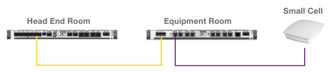
Image courtesy of Panduit.
- Carrier dependent
- Internet based
- No SLA
- Doesn’t always scale well
| Type | Power | Coverage | Capacity | Use Case |
|---|---|---|---|---|
| Femtocell | 0.1 Watt | 60 ft. | 6 users | Indoors |
| Picocell | 1 Watt | 750 ft. | 64 users | Indoors |
| Metrocell | 5 Watts | 1,000 ft. | 200 users | Indoors/Outdoors |
| Microcell | 10 Watts | 5,000 ft. | 1,000 users | Indoors/Outdoors |
DAS Types
Passive
- RF couplings
- Splitters
- Taps
- Wires
Hybrid
- Fiber
- RF is carried via coax to passive antennas
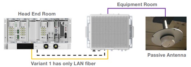
Image courtesy of Panduit.
Active
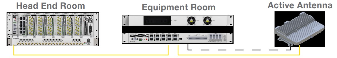
Image courtesy of Panduit.
- Fiber
- Active antennas generate their own RF
References
Panduit - In-Building Wireless Reference Architecture
ATT - Managed In-Building Solution
Boot with TFTP
This is meant for IOS or IOS-XE.
This was done in Packet Tracer, but the theory is the same.
If the IP is reachable, and the TFTP server has the image, it should work.
rommon 8 >
rommon 8 > IP_ADDRESS=192.168.12.2
rommon 9 > IP_SUBNET_MASK=255.255.255.252
rommon 10 > DEFAULT_GATEWAY=192.168.12.1
rommon 11 > TFTP_SERVER=10.0.0.1
rommon 12 > TFTP_FILE=c2900-universalk9-mz.SPA.155-3.M4a.bin
rommon 13 > set
PS1=rommon ! >
DEFAULT_GATEWAY=192.168.12.1
IP_ADDRESS=192.168.12.2
IP_SUBNET_MASK=255.255.255.252
TFTP_FILE=c2900-universalk9-mz.SPA.155-3.M4a.bin
TFTP_SERVER=10.0.0.1
rommon 14 > tftpdnld
[output omitted]
program flash location 0x61fc0000
program flash location 0x61fd0000
program flash location 0x61fe0000
program flash location 0x61ff0000
program flash location 0x62000000
rommon 23 > boot
System Bootstrap, Version 15.1(4)M4, RELEASE SOFTWARE (fc1)
Technical Support: http://www.cisco.com/techsupport
Copyright (c) 2010 by cisco Systems, Inc.
Total memory size = 512 MB - On-board = 512 MB, DIMM0 = 0 MB
CISCO2911/K9 platform with 524288 Kbytes of main memory
Main memory is configured to 72/-1(On-board/DIMM0) bit mode with ECC disabled
Readonly ROMMON initialized
program load complete, entry point: 0x80803000, size: 0x1b340
References
Telnet with no user accounts
A tech from an earlier time.
- No encryption
- No user accounts
- Requires two passwords
- Line password
- Enable password
Applying aaa new-model will immediately remove the login lines, breaking login.
Tested on IOSv, Version 15.9(3)M8.
Config
This is the minimum to get this feature working.
!
! Defaults to off, just a reminder it needs to be off.
!
no aaa new-model
!
! Put a password here, or enable will not work
!
! Can also use enable secret
!
enable password Cisco123
!
! I didn't want to configure an IP.
!
! The device needs an IP for Telnet to work.
!
interface GigabitEthernet0/0
ip address dhcp hostname r2-aaa
!
! Each set of vty lines require three things:
!
! 1. login
! 2. password
! 3. transport method
!
line vty 0 4
password Cisco123
login
transport input telnet
line vty 5 15
password Cisco123
login
transport input telnet
References
Sitemaps
Helpful for webcrawlers to properly index a website.
One way to get the sitemap easier to find is putting the location in the robots.txt file.
Tips
- Google ignores
<priority> - Google checks
<lastmod>for accuracy
… and accurate sitemap leads to better SEO.
Example from www.sitemaps.org
<?xml version="1.0" encoding="UTF-8"?>
<urlset xmlns="http://www.sitemaps.org/schemas/sitemap/0.9">
<url>
<loc>http://www.example.com/</loc>
<lastmod>2005-01-01</lastmod>
<changefreq>monthly</changefreq>
<priority>0.8</priority>
</url>
</urlset>
Source sitemaps.org/protocol.
This site - pushpopswap.com
Of course, this site’s sitemap.xml file is built on compile time, see the script here.
References
Socket Statistics
SS — Socket Statistics
Is Samba working?
-l - listening
-t - tcp
-n - numeric
-p - processes
ss -ltnp | grep smbd
Kubernetes on Debian - Initial Setup
An older provisioning method, using MetalLB.
I add my nodes to DNS so everything resolves nicely.
- k8s-tiny-1-control
- k8s-tiny-2-control
- k8s-tiny-3-control
- k8s-tiny-4-worker
- k8s-tiny-5-worker
- k8s-tiny-6-worker
- k8s-tiny-7-worker
- k8s-agatha-worker
Turn off swap
sudo swapoff -a
sudo sed -i '/ swap / s/^\(.*\)$/#\1/g' /etc/fstab
Edit sysctl variables
cat <<EOF | sudo tee /etc/sysctl.d/99-kubernetes-k8s.conf
net.bridge.bridge-nf-call-iptables = 1
net.ipv4.ip_forward = 1
net.bridge.bridge-nf-call-ip6tables = 1
EOF
Modprobe for containerd
cat <<EOF | sudo tee /etc/modules-load.d/containerd.conf
overlay
br_netfilter
EOF
sudo modprobe overlay
sudo modprobe br_netfilter
sudo sysctl --system
Install containerd
Update APT
sudo apt-get update
sudo apt-get install \
ca-certificates \
curl \
gnupg \
lsb-release
Add Docker’s GPG Keys
sudo mkdir -p /etc/apt/keyrings
curl -fsSL https://download.docker.com/linux/debian/gpg | sudo gpg --dearmor -o /etc/apt/keyrings/docker.gpg
Add Repo
echo \
"deb [arch=$(dpkg --print-architecture) signed-by=/etc/apt/keyrings/docker.gpg] https://download.docker.com/linux/debian \
$(lsb_release -cs) stable" | sudo tee /etc/apt/sources.list.d/docker.list > /dev/null
Add Containerd. Mark as do-not-upgrade
sudo apt update
sudo apt install containerd.io -y
sudo apt-mark hold containerd.io
Modify containerd so it uses cgroups with systemd
containerd config default | sudo tee /etc/containerd/config.toml >/dev/null 2>&1
sudo sed -i 's/SystemdCgroup = false/SystemdCgroup = true/' /etc/containerd/config.toml
Enable and restart containerd
sudo systemctl restart containerd
sudo systemctl enable containerd
Enable Kubernetes repo
sudo apt install gnupg gnupg2 curl software-properties-common -y
This is version’d and pinned to 1.30
curl -fsSL https://pkgs.k8s.io/core:/stable:/v1.30/deb/Release.key | sudo gpg --dearmor -o /etc/apt/keyrings/kubernetes-apt-keyring.gpg
echo 'deb [signed-by=/etc/apt/keyrings/kubernetes-apt-keyring.gpg] https://pkgs.k8s.io/core:/stable:/v1.30/deb/ /' | sudo tee /etc/apt/sources.list.d/kubernetes.list
Install Kubelet, Kubectl, and Kubeadm … Mark as do-not-upgrade
sudo apt update
sudo apt install kubelet kubeadm kubectl -y
sudo apt-mark hold kubelet kubeadm kubectl
Add Control Plane Node
On a control node
Put the active PKI certificates into a Secret that can be accessed with a certificate key. All control nodes need matching PKI certs (?).
sudo kubeadm init phase upload-certs --upload-certs
Copy the very long key
Get a new token
sudo kubeadm token create --print-join-command
Build the Command to add the new control node
Use the following on the new node
sudo kubeadm join k8s-master:6443 --token <the-token>\
--discovery-token-ca-cert-hash sha256:<the-sha256>\
--certificate-key <the-key>\
--control-plane
Add worker Node
sudo kubeadm join k8s-master:6443 --token <the-token> \
--discovery-token-ca-cert-hash sha256:<the-sha256>
Flannel Setup
kubectl apply -f https://github.com/flannel-io/flannel/releases/latest/download/kube-flannel.yml
Turn on Metal-LB
See MetalLB in L2 for the controller/speaker model and L2 behavior.
Deploy Manifests
kubectl apply -f https://raw.githubusercontent.com/metallb/metallb/v0.13.10/config/manifests/metallb-native.yaml
Config
cat <<EOF > ~/my-metallb.yaml
apiVersion: metallb.io/v1beta1
kind: IPAddressPool
metadata:
name: vlan-42-pool
namespace: metallb-system
spec:
addresses:
- 192.168.42.64-192.168.42.95
---
apiVersion: metallb.io/v1beta1
kind: L2Advertisement
metadata:
name: vlan-42-l2-advertisement
namespace: metallb-system
spec:
ipAddressPools:
- vlan-42-pool
EOF
wait a few moments after deploying the manifests above
ariadne@k8s-control-tiny-1:~$ kubectl apply -f ~/my-metallb.yaml
ipaddresspool.metallb.io/vlan-42-pool created
l2advertisement.metallb.io/vlan-42-l2-advertisement created
Both of these need to be created for it to work. It can be two files… kubectl didn’t tell me the syntax was wrong for one of the stanzas.
References
Install Docker Engine on Ubuntu | Docker Docs
Flannel VXLAN
I want to understand what I’m implementing. I started with this. I did not implement it.
I went with host-gw for backend.
Flannel v0.28.5:
- backend: Linux VXLAN
- interface: flannel.1
- VNI: 1
- port: UDP/8472
- directRouting: disabled
Control Plane
sequenceDiagram
participant K8sAPI as Kubernetes API
participant fA as Node A<br>flanneld
participant kA as Node A<br>Linux kernel
participant fB as Node B<br>flanneld
Note over K8sAPI,fB: Initialization followed by continuous node/lease event handling
fA->>K8sAPI: Read local Node PodCIDR
K8sAPI-->>fA: 10.244.1.0/24
fA->>kA: Create flannel.1 (VXLAN VNI 1, dstport 8472)
fA->>K8sAPI: Patch Node A annotations with backend type,<br>VTEP MAC, VNI, and public IP
fA->>kA: Assign 10.244.1.0/32 to flannel.1 and set link up
fA->>fA: Write /run/flannel/subnet.env
fA->>K8sAPI: Consume Node/lease events continuously
fB->>K8sAPI: Perform the same initialization for 10.244.2.0/24
fB->>K8sAPI: Patch Node B annotations with its VTEP information
K8sAPI-->>fA: Node B lease event: PodCIDR,<br>VTEP MAC, VNI, and public IP
Note over fA,kA: Install entries in this order so adding the route<br>cannot trigger unresolved neighbor discovery
fA->>kA: 1) Neighbor: 10.244.2.0 -> Node B VTEP MAC (PERMANENT)
fA->>kA: 2) FDB: Node B VTEP MAC -> Node B public IP<br>(self, PERMANENT)
fA->>kA: 3) Route: 10.244.2.0/24 via 10.244.2.0<br>dev flannel.1, on-link
Data Plane
cni0 and the pod veth interfaces are created by the CNI bridge plugin, not by
Flannel.
This example also assumes IP forwarding and the required firewall policy are already in place.
sequenceDiagram
participant PodA as Pod A<br>10.244.1.5
participant cni0A as Node A<br>cni0
participant kA as Node A<br>Linux IP stack
participant flanA as Node A<br>flannel.1 - VTEP
participant ethA as Node A<br>eth0 - 192.168.1.11
participant ethB as Node B<br>eth0 - 192.168.1.12
participant flanB as Node B<br>flannel.1 - VTEP
participant kB as Node B<br>Linux IP stack
participant cni0B as Node B<br>cni0
participant PodB as Pod B<br>10.244.2.7
Note over PodA,PodB: Data plane — single packet, Pod A to Pod B
PodA->>cni0A: Send packet for 10.244.2.7 to its default gateway
cni0A->>kA: Deliver packet to the host IP stack
kA->>flanA: Route lookup selects 10.244.2.0/24<br>via next-hop 10.244.2.0
flanA->>flanA: 1) Neighbor lookup: 10.244.2.0 -> Node B VTEP MAC
flanA->>flanA: 2) FDB lookup: Node B VTEP MAC -> dst 192.168.1.12 (static)
flanA->>ethA: 3) VXLAN encapsulate (UDP/8472, VNI 1)
ethA->>ethB: VXLAN/UDP over underlay L3
ethB->>flanB: 4) Decapsulate and present the inner Ethernet frame
flanB->>kB: Frame is addressed to Node B's VTEP MAC
kB->>kB: 5) Route inner packet using<br>10.244.2.0/24 dev cni0
kB->>cni0B: 6) Resolve 10.244.2.7 to the pod MAC<br>and emit the Ethernet frame
cni0B->>PodB: Bridge FDB selects the pod veth and delivers the frame
References
Flannel v0.28.5 VXLAN backend - vxlan.go
Flannel v0.28.5 VXLAN network event handling - vxlan_network.go
Flannel v0.28.5 VXLAN device implementation - device.go
Flannel v0.28.5 Kubernetes subnet manager - kube.go
Flannel change the spec.podCIDR subnets
Warning
This is involved and non-trivial. It is a completely unsupported path.
Caution
spec.podCIDRcannot be modified. It must be removed then added back.
Normally, flannel encapsulates the pod packets inside of VXLAN … but if you have a layer 2 setup, you don’t need VXLAN.
My Kubernetes Equipment VLAN: 192.168.44.0/24
I realized I wanted this IP scheme after I had already deployed Kubernetes :/
| Hostname | Node IP | Subnet |
|---|---|---|
| k3s-tiny-1-control | 192.168.44.11 | 10.44.1.0/24 |
| k3s-tiny-2-control | 192.168.44.12 | 10.44.2.0/24 |
| k3s-tiny-3-control | 192.168.44.13 | 10.44.3.0/24 |
| k3s-tiny-4-worker | 192.168.44.24 | 10.44.4.0/24 |
| k3s-tiny-5-worker | 192.168.44.25 | 10.44.5.0/24 |
| k3s-tiny-6-worker | 192.168.44.26 | 10.44.6.0/24 |
| k3s-tiny-7-worker | 192.168.44.27 | 10.44.7.0/24 |
No VXLAN - using host-gw
host-gw turns on plain layer 3 routing.
This removes a tremendous amount of container networking complexity.
Console
ariadne@k3s-worker-tiny-5:~$ ip route
default via 192.168.44.1 dev eth0 proto static
10.44.1.0/24 via 192.168.44.11 dev eth0
10.44.2.0/24 via 192.168.44.12 dev eth0
10.44.3.0/24 via 192.168.44.13 dev eth0
10.44.4.0/24 via 192.168.44.24 dev eth0
10.44.5.0/24 dev cni0 proto kernel scope link src 10.44.5.1
10.44.6.0/24 via 192.168.44.26 dev eth0
10.44.7.0/24 via 192.168.44.27 dev eth0
192.168.44.0/24 dev eth0 proto kernel scope link src 192.168.44.25
Graphed
graph TD
HUB((VLAN 44<br/>192.168.44.0/24))
N1["k3s-tiny-1-control<br/>192.168.44.11"]
N2["k3s-tiny-2-control<br/>192.168.44.12"]
N3["k3s-tiny-3-control<br/>192.168.44.13"]
N4["k3s-tiny-4-worker<br/>192.168.44.24"]
N5["k3s-tiny-5-worker<br/>192.168.44.25"]
N6["k3s-tiny-6-worker<br/>192.168.44.26"]
N7["k3s-tiny-7-worker<br/>192.168.44.27"]
S1[["10.44.1.0/24"]]
S2[["10.44.2.0/24"]]
S3[["10.44.3.0/24"]]
S4[["10.44.4.0/24"]]
S5[["10.44.5.0/24"]]
S6[["10.44.6.0/24"]]
S7[["10.44.7.0/24"]]
HUB --- N1
HUB --- N2
HUB --- N3
HUB --- N4
HUB --- N5
HUB --- N6
HUB --- N7
N1 --- S1
N2 --- S2
N3 --- S3
N4 --- S4
N5 --- S5
N6 --- S6
N7 --- S7
classDef control fill:#2d5f8a,stroke:#1a3a52,color:#fff
classDef worker fill:#3a7d3a,stroke:#1f4a1f,color:#fff
classDef hub fill:#8a2d2d,stroke:#521a1a,color:#fff
classDef subnet fill:#5a5a5a,stroke:#333,color:#fff
class N1,N2,N3 control
class N4,N5,N6,N7 worker
class HUB hub
class S1,S2,S3,S4,S5,S6,S7 subnet
Prerequisites
- K3S
- All K3S nodes on the same VLAN
- No firewall between nodes
- SSH access to every node
- 3 control nodes, to keep quorum
- Backups or nothing important on this cluster
Migration Plan
- Back up first
- Update Flannel
- Restart K3S
- Reassign each Pod CIDR
- Verify the new allocation
- Verify traffic
- Clean up stale routes
Step-by-Step
1. Back up first
I made backups of my VMs.
2. Update Flannel
This does a few things:
- Specifies the network plan for this cluster
- Turns off VXLAN
- Turns off auto allocation
/etc/rancher/k3s/config.yaml
These are the values to add.
flannel-backend: host-gw
cluster-cidr: 10.44.0.0/16
kube-controller-manager-arg:
- allocate-node-cidrs=false
This file doesn’t always already exist, if it doesn’t you can use this.
sudo tee -a /etc/rancher/k3s/config.yaml >/dev/null <<'EOF'
flannel-backend: host-gw
cluster-cidr: 10.44.0.0/16
kube-controller-manager-arg:
- allocate-node-cidrs=false
EOF
3. Restart K3S
- Restart one control node at a time
- Wait until back to 3 of 3 quorum
sudo systemctl restart k3s
4. Reassign each Pod CIDR
spec.podCIDR cannot be modified. It must be removed then added back.
On the node — SSH or Console
Via API — Point at a control node that has quorum
- This is performed in sequence, one node at a time
- This is eventually performed on all nodes
- Changes made via API must always be to a control node with quorum
- This is slow and tedious
Tip
For this example I’m modifying
k3s-tiny-1-controlso I point the API atk3s-tiny-2-control
-
On the node - Stop K3s and delete the old CNI info
sudo systemctl stop k3s # controllers sudo systemctl stop k3s-agent # workers sudo ip link del cni0 # still holds the OLD gateway IP sudo rm -rf /var/lib/cni/* sudo rm -f /run/flannel/subnet.env sudo ip link del flannel.1 2>/dev/null # leftover VXLAN device, if present -
Via API - Delete the Node object
Necessary to remove
podCIDR.Caution
Delete the node you’re repinning — never the controller you pointed the API at. Deleting the wrong controller evicts a healthy etcd member. Do that while another controller is already down and you drop below quorum.
kubectl delete node k3s-tiny-1-control \ --server=https://k3s-tiny-2-control:6443 \ --insecure-skip-tls-verify -
(If controller) On the node - Move etcd
We are going to re-join this node later. This etcd won’t be used.
sudo mv /var/lib/rancher/k3s/server/db/etcd \ /var/lib/rancher/k3s/server/db/etcd.removed-$(date +%s) -
On the node - Start K3s
The device should re-join.
K3S has settings for this in:
/etc/systemd/system/k3s.serviceor/etc/rancher/k3s/config.yaml
sudo systemctl start k3s -
Via API - Wait for it to re-register with an empty PODCIDR
kubectl get node k3s-tiny-1-control \ -o jsonpath='{.spec.podCIDR}{"\n"}' \ --server=https://k3s-tiny-2-control:6443 \ --insecure-skip-tls-verify -
Via API - Patch the exact CIDR you want
kubectl patch node k3s-tiny-1-control --type=merge \ -p '{"spec":{"podCIDR":"10.44.1.0/24","podCIDRs":["10.44.1.0/24"]}}' \ --server=https://k3s-tiny-2-control:6443 \ --insecure-skip-tls-verify
5. Verify the new allocation
Each node should receive a unique /24 from 10.44.0.0/16.
Check the node annotations and routes on every machine.
kubectl get nodes -o wide
ip route | grep 10.44
6. Verify traffic
Test three paths:
- pod to pod on different nodes
- pod to ClusterIP
- pod to API VIP or external service
Use temporary test pods and remove them afterward.
7. Clean up stale routes
You might have to clean up old routes.
Log into each node and check.
See the example.
Log into each node and check for sanity
ip route
To delete
sudo ip route del 10.44.9.0/24
References
MetalLB in L2
Kubernetes architecture requires a LoadBalancer.
MetalLB can be deployed as a LoadBalancer in L2 mode, which is good for bare metal homelab style environments.
Example Deployment
deployment/controller 1 replica
daemonset/speaker 7 pods
Theory
Controller
- Watches for
LoadBalancerrequest - Picks a free IP out of the pool
- Assigns it to the Service as its EXTERNAL-IP
Speaker
- bound to
hostNetwork - Runs stateless hash
- First on the list advertise the MetalLB IPs
L2 Operation
Is the service running?
kubectl get l2advertisements -n metallb-system
What services are consuming an IP?
kubectl get svc -A --field-selector spec.type=LoadBalancer
How the L2 leader election works
- Stateless
- Creates a list of all speakers could announce the IP.
- Sorts the list with a specific hash.
- First speaker on the list announces the IP (responds to ARP).
References
Cisco ACI
Cisco Certifications
Cisco - Career Certification Pathway
Performance Based Labs
https://blogs.cisco.com/learning/new-performance-based-lab-exam-items-build-opportunities
IPv4 to Hex
This uses in browser javascript.
IPv4 to hexadecimal converter
EIGRP Classic Metric
The RFC recommended way to modify a path with EIGRP is changing the delay, under the interface. This will not impact other protocols. Modifying bandwidth … affects lots of things!
EIGRP classic mode 32-bit composite metric calculator per RFC 7868 section 5.6.1.1
RFC 7868 Cisco's EIGRP May 2016
5.6.1.1. Classic Composite Formulation
EIGRP calculates the composite metric with the following formula:
metric = 256 * ({(K1*BW) + [(K2*BW)/(256-LOAD)] + (K3*DELAY)} *
(K5/(REL+K4)))
In this formula, Bandwidth (BW) is the lowest interface bandwidth
along the path, and delay (DELAY) is the sum of all outbound
interface delays along the path. Load (LOAD) and reliability (REL)
values are expressed percentages with a value of 1 to 255.
Implementation note: Cisco IOS routers display reliability as a
fraction of 255. That is, 255/255 is 100% reliability or a perfectly
stable link; a value of 229/255 represents a 90% reliable link. Load
is a value between 1 and 255. A load of 255/255 indicates a
completely saturated link. A load of 127/255 represents a 50%
saturated link. These values are not dynamically measured; they are
only measured at the time a link changes.
Bandwidth is the inverse minimum bandwidth (in kbps) of the path in
bits per second scaled by a factor of 10^7. The formula for
bandwidth is as follows:
(10^7)/BWmin
Implementation note: When converting the real bandwidth to the
composite bandwidth, truncate before applying the scaling factor.
When converting the composite bandwidth to the real bandwidth, apply
the scaling factor before the division and only then truncate.
The delay is the sum of the outgoing interface delay (in tens of
microseconds) to the destination. A delay set to it maximum value
(hexadecimal 0xFFFFFFFF) indicates that the network is unreachable.
The formula for delay is as follows:
[sum of delays]
The default composite metric, adjusted for scaling factors, for EIGRP
is:
metric = 256 * { [(10^7)/ BWmin] + [sum of delays]}
Validation
R1# show ip protocols | i weight
Metric weight K1=2, K2=2, K3=2, K4=0, K5=0
R1# show ip eigrp topology 10.0.0.0
EIGRP-IPv4 Topology Entry for AS(100)/ID(1.1.1.1) for 10.0.0.0/8
State is Passive, Query origin flag is 1, 1 Successor(s), FD is 6164
Descriptor Blocks:
192.168.12.2 (GigabitEthernet0/0), from 192.168.12.2, Send flag is 0x0
Composite metric is (6164/5652), route is Internal
Vector metric:
Minimum bandwidth is 1000000 Kbit
Total delay is 20 microseconds
Reliability is 255/255
Load is 1/255
Minimum MTU is 1500
Hop count is 1
Originating router is 2.2.2.2
References
RFC 7868 - Cisco’s Enhanced Interior Gateway Routing Protocol (EIGRP)
EIGRP Wide Metric
The RFC recommended way to modify a path with EIGRP is changing the delay, under the interface. This will not impact other protocols. Modifying bandwidth … affects lots of things!
This calculator uses the EIGRP values from the RFC, in table 5.6.1.2.
EIGRP named mode 64-bit wide metric calculator per RFC 7868 with correct interface delay constants
Wide network vectors
RFC 7868 Cisco's EIGRP May 2016
5.6.2.1. Wide Metric Vectors
EIGRP uses five "vector metrics": minimum Throughput, latency, load,
reliability, and MTU. These values are calculated from destination
to source as follows:
o Throughput - Minimum value
o Latency - accumulative
o Load - maximum
o Reliability - minimum
o MTU - minimum
o Hop count - accumulative
There are two additional values: Jitter and energy. These two values
are accumulated from destination to source:
o Jitter - accumulative
o Energy - accumulative
Wide metric conversion constants
RFC 7868 Cisco's EIGRP May 2016
5.6.2.2. Wide Metric Conversion Constants
EIGRP uses a number of defined constants for conversion and
calculation of metric values. These numbers are provided here for
reference
EIGRP_BANDWIDTH 10,000,000
EIGRP_DELAY_PICO 1,000,000
EIGRP_INACCESSIBLE 0xFFFFFFFFFFFFFFFFLL
EIGRP_MAX_HOPS 100
EIGRP_CLASSIC_SCALE 256
EIGRP_WIDE_SCALE 65536
When computing the metric using the above units, all capacity
information will be normalized to kilobytes and picoseconds before
being used. For example, delay is expressed in microseconds per
kilobyte, and would be converted to kilobytes per second; likewise,
energy would be expressed in power per kilobytes per second of usage.
Throughput
RFC 7868 Cisco's EIGRP May 2016
5.6.2.3. Throughput Calculation
The formula for the conversion for Max-Throughput value directly from
the interface without consideration of congestion-based effects is as
follows:
(EIGRP_BANDWIDTH * EIGRP_WIDE_SCALE)
Max-Throughput = K1 * ------------------------------------
Interface Bandwidth (kbps)
If K2 is used, the effect of congestion as a measure of load reported
by the interface will be used to simulate the "available Throughput"
by adjusting the maximum Throughput according to the formula:
K2 * Max-Throughput
Net-Throughput = Max-Throughput + ---------------------
256 - Load
K2 has the greatest effect on the metric occurs when the load
increases beyond 90%.
Latency
RFC 7868 Cisco's EIGRP May 2016
5.6.2.4. Latency Calculation
Transmission times derived from physical interfaces MUST be n units
of picoseconds, converted to picoseconds prior to being exchanged
between neighbors, or used in the composite metric determination.
This includes delay values present in configuration-based commands
(i.e., interface delay, redistribute, default-metric, route-map,
etc.).
The delay value is then converted to a "latency" using the formula:
Delay * EIGRP_WIDE_SCALE
Latency = K3 * --------------------------
EIGRP_DELAY_PICO
Composite calculation
RFC 7868 Cisco's EIGRP May 2016
5.6.2.5. Composite Calculation
K5
metric =[(K1*Net-Throughput) + Latency)+(K6*ExtAttr)] * ------
K4+Rel
By default, the path selection scheme used by EIGRP is a combination
of Throughput and Latency where the selection is a product of total
latency and minimum Throughput of all links along the path:
metric = (K1 * min(Throughput)) + (K3 * sum(Latency)) }
Validations
R1# show eigrp address-family ipv4 topology 2.2.2.2/32
EIGRP-IPv4 VR(EIGRP_100) Topology Entry for AS(100)/ID(1.1.1.1) for 2.2.2.2/32
State is Passive, Query origin flag is 1, 7 Successor(s), FD is 1392640, RIB is 10880
Descriptor Blocks:
10.12.1.2 (GigabitEthernet0/1), from 10.12.1.2, Send flag is 0x0
Composite metric is (1392640/163840), route is Internal
Vector metric:
Minimum bandwidth is 1000000 Kbit
Total delay is 11250000 picoseconds
Reliability is 255/255
Load is 1/255
Minimum MTU is 1500
Hop count is 1
Originating router is 2.2.2.2
Validation
R1# show ip protocols | i weight
Metric weight K1=1, K2=2, K3=3, K4=4, K5=5 K6=0
R1# show ip eigrp topology 2.2.2.2/32
EIGRP-IPv4 VR(EIGRP_100) Topology Entry for AS(100)/ID(1.1.1.1) for 2.2.2.2/32
State is Passive, Query origin flag is 1, 7 Successor(s), FD is 55450, RIB is 433
Descriptor Blocks:
10.12.1.2 (GigabitEthernet0/1), from 10.12.1.2, Send flag is 0x0
Composite metric is (55450/6338), route is Internal
Vector metric:
Minimum bandwidth is 1000000 Kbit
Total delay is 11250000 picoseconds
Reliability is 255/255
Load is 1/255
Minimum MTU is 1500
Hop count is 1
Originating router is 2.2.2.2
References
RFC 7868 - Cisco’s Enhanced Interior Gateway Routing Protocol (EIGRP)
Other Resources
Blogs
Chris’s CCIE Study Blog - CCIE Enterprise
Blame The Network - Kelvin Tran
Videos
Jeremy’s IT Lab | Free CCNA & Anki Flashcards, CCNA 200-301 Complete Course - YouTube
Etc
Style Guide
Definitions
Headings use sentence case, it’s a touch more casual and less commanding
MPL — Modern Parking Lot
- Uses CommonMark
- Bold for the abbreviation, which is used in common speech
- Expansion goes next to it with a hyphen train
- Items go underneath as bullets
- Sort of resembles a parking lot
- Never has periods on the end
- Sentence case
- No periods on the end
A - Single hyphen, Nope
Two – hyphens, Nope
Hyphen Train — Uses three hyphens. Good. Don’t bold the definition
- This is a modern definition
- It uses the colon in front, but there is no easy way to do line breaks. It’s weird about where it puts the first indent. It’s also like, very tightly spaced?
I guess this would be good for prose? Nope, doesn’t respect indents.
- Just bolds the whole thing
- There’s a line space above the top bullet
- Items like to be off by themselves
Admonish
Note
General information or additional context.
Tip
A helpful suggestion or best practice.
Important
Key information that shouldn’t be missed.
Warning
Critical information that highlights a potential risk.
Caution
Information about potential issues that require caution.
SUMMARY.md
<-- Section should be a large inclusive word, because it will show up in the URIs -->
# Routing
<-- All files go into same same section folder -->
- [OSPFv2](./ospf/ospfv2.md) <-- Root -->
- [DR Election](./ospf/ospfv2-dr-election.md) <-- Sidebar_Branch_Title is short, branch_name_is_qualified -->
- [DR LSAs](./ospf/ospfv2-dr-lsas.md) <-- Sidebar_Leaf_Title is short, leaf_file_name_is_qualified -->
Footnote
This is a footnote1.
Links
Theme break
A code block
never use this
it can't be found
because its not fenced
A good numbered list
1. It needs to be bolded on the top
- It looks good
- Bold catches the eyes
2. Keep Numbering
- Everything will work out fine
A bad numbered list
- This doesn’t work.
- Nope
- Not at all
- Seems like it should
- But it doesn’t
Reference
Markdown - mdBook Documentation
-
This text is the contents of the footnote, which will be rendered ↩
CCIE Blogs
50931 - Katherine McNamara
57783 - Ivan Ivanov
58825 - Jacob Zartmann
Troubleshooting
How did we get here?
The problems don’t happen in a vacuum. The network was working, until it wasn’t.
Did it …
- Just break?
- Its been broken?
- Its been working for a while then broke?
- Its never worked?
Does it happen …
- All the time?
- Sometimes?
- Just this once?
- At every site?
- Just this site?
- On weekends?
Can you take a photo?
Is this the kind of problem that would be easier if there was a photo?
Are there logs?
Is this the kind of problem that would show up in a log?
Baseline
What can you collect to understand how this problem is different, odd, special, or unique compared to other similar problems?
Customer Service
“Nobody cares what you know, until they know that you care”
BASICS
Breathe - Prepare to take the call. Get into the mindset.
Answer - The phone in 2-3 rings
Say - Say your name and team. Ask theirs.
Indicate - What will you do?
Courteous - Sound concerned
Smiling - People can hear your smile!
Q-TIP
Quit Taking Things Personally
Never ask a Customer to calm down.
You may have been asked to work a network outage. This might be one of the worst days of this customer’s professional life. They might be fired after this.
If the customer is getting more and more agitated, remember, the problem is solved or it isn’t. This is a team sport, many people are involved and we don’t always know the stakes.
As the call heats up, get others involved. Let your team know what’s going on. Make the problem visible.
If the customer starts to vent, do not stop them, it isn’t about you, it’s about the problem. They will feel catharsis getting it out.
If they are rude or unprofessional, once the problem is solved, they will understand the lapse in their own behavior and apologize.
Why do customers complain?
- Projection of “can’t do” attitude
- No one listened
- No one went out of their way
- Someone was rude to the customer
- They didn’t receive what they were promised or expected
Why complaints are good
- Every complaint represents about 25 other people
- If someone complains, they typically won’t buy from you again
- If you impress a complainer, you can actually get new business
Basic strategic objectives
1. Pace the customer’s emotional state
Speed up if they are agitated, slow down if they are relaxed. Respond to the call’s urgency.
2. Communicate that you understand
Use empathy statements like ‘I understand’, ‘I see …’
3. Gather the information you need
Ask, “Can I ask you some questions?”
4. Transition to your agenda
Get consent, “May we begin troubleshooting?”
5. Offer solutions and solve the problem
“I want to try this, here is the impact.”
Improving listening skills
If you are writing things down, you are probably listening. What to listen for:
- Dates
- Times
- Events
- Conditions
- People
- Vibe
Pen and paper is silent and cannot crash.
Pen and paper can make good topology diagrams, and occupy your hands.
- Listen for ideas
- Delay evaluation
- Just listen
- Find an area of interest
- Avoid spending time getting read to talk and only listen
- Do only one thing at a time
- Only listen
- Do only one thing at a time
- Keep your mind open
Advanced listening skills
- What are they saying?
- What would they like to say?
- How does their emotional state influence their emotional state?
Consent
- “How do you feel about the Action Plan?”
- “Do you understand our next steps?”
- “I can get a summary email out by close of business, is that OK?”
What creates “hard-to-please customers”
- Using the word “policy”
- Monotone
- Too fast
- Interrupting
- Lack of interest
- Lack of empathy
- Excuses
- JADE: justify, argue, defend or explain
Magic words and phrases
- Acknowledge the seriousness of the situation
- Make empathetic statements
- Acknowledge how their emotions are valid
- Use their name
- Give personal assurance
- “I apologize”
- X will happen on Y
Mute
Use it sparingly.
The customer wants to know how you are spending their time. It’s safer to stay audible and say things like …
- “I’m doing some research”
- “I’m seeing if this is a common problem”
- “I’m letting my team know what’s going on”
- “I’m looking at possible bugs”
- “I’m finding internal documents”
- “I’m finding the deployment guide.”
Long mutes are dangerous and hurt sentiment.
Profanity
“I’m having a difficult time hearing you because of the profanity being used. If we could discontinue using those words, I could help you to get the results you want much quicker. Is that OK?”
Accents
“I’m having a difficult time understanding you, could you speak slower?”
Bad connections
“I’m sorry, do you have a different phone you could use? It’s very difficult to understand you.”
International call etiquette
Avoid Idioms.
Case handling
“In order to save time I’d like to ask some questions to scope the problem. They might seem basic, is that OK?”
Bathroom visits
“I’m going to step away for a few moments, I’ll be right back.”
References
A Woman Calls TAC
Heard joke once: Woman calls TAC.
Says switch is busted.
Says switch seems buggy and unstable.
Says switch required an upgrade, the software was End-of-Life.
TAC goes, “Action Plan is simple. Work with HTTS, Go and see them. That should pick you up.”
Woman bursts into tears. Says, “ … but I am HTTS.“
Good joke. Everybody laughs. Roll on snare drum. Curtains.
A Red Team Housecall
This makes its way around the Internet. I rewrote it for technical accuracy.
Girl invited me over to “fix her WiFi.” I am a red team engineer with custom firmware on my router and no IoT devices.
I showed up 10 minutes early, hoodie on, my laptop loaded with a hardened gentoo install I self-compiled.
She opened the door holding a MacBook Air. I saw she had chrome installed with 43 tabs open. I almost left right then.
“Can I see a network diagram?” She laughed. “It’s just the router from the ISP.”
Alright … Let her have it.
I popped open her router admin panel, with a default password:
admin123. The SSID was “PrettyFlyForAWiFi”. I rannmapscan.
- No firewall
- 1 subnet, no vlans
- 12 exposed ports
- 3 outdated IoT devices
- A printer running telnet.
… raw digital nudity.
“Do you ever get lag?”
“What’s lag?”
“Is the network slow?” “yeah sometimes Netflix buffers.”
I loaded up Wireshark, attaching it to the LAN side of the network. My machine is sluggish under the load of packets, I need to stop the capture to see the stream. I check the IPs and find they are located in several East European countries.
“So your TV is on the wifi, huh?”
“Yeah, but I never use the smart features, it’s too slow”
“Do you update it?”
“Update what?”
… I’m struggling to stay composed. I reframe.
“Update the software on the TV. Your network will be much faster if you just … take the TV off the wifi. Your … TV looks to be participating in a botnet.”
“Is that bad?”
“It isn’t good.”
I offered to segment the network and install pfSense. She said she “just wanted Spotify to stop cutting out.”
I airgapped her Sonos out of pity.
After 20 minutes of work, I asked for her phone to remove TikTok and clean the app permissions. She said “but I need it for filters.” I looked into the distance. Deep sigh. I looked out the window and whispered …
“The panopticon isn’t metaphorical.” “Are you always this intense?”
“No, only when the NSA is listening.” … Which is always.
She offered coffee. I declined, caffeine raises your attack surface.
I get up to leave, she goes, “Thanks, you’re like, really good with computers.”
I walked away slow. Her router was still on UPnP. So was my heart. You can’t patch people. Believe me, I tried.
// date_night_final_final_forsure.txt.gpg#exit